Quantitative cerebrospinal fluid diversion system and method

A quantitative shunt and cerebrospinal fluid technology, applied in the field of neurosurgery cerebrospinal fluid shunt system, can solve the problems of secondary surgery pain, huge economic burden, sudden increase in ventricular system pressure, and increased labor costs, so as to promote research and improve the level of diagnosis and treatment, prevent The effect of excessive shunt and cerebrospinal fluid reflux, and the probability of tube blockage is small

Active Publication Date: 2020-10-13
兴化市人民医院 +2
View PDF9 Cites 0 Cited by
  • Summary
  • Abstract
  • Description
  • Claims
  • Application Information

AI Technical Summary

Problems solved by technology

This brings unnecessary secondary surgery pain and huge economic burden to patients
[0006] The second type is an adjustable pressure shunt system. Patient pressure adjustment requires special pressure adjustment tools and equipment, as well as professional and technical personnel to operate, which brings inconvenience to patients and increases labor costs.
For patients who have been installed with traditional ventriculoperitoneal shunt and lumbar-peritoneal shunt system, under such pressure fluctuations, excessive shunting of cerebrospinal fluid may occur.
The traditional ventriculoperitoneal shunt and lumbar-peritoneal shunt system are difficult to control this transitional shunt
[0008] The fourth is that the traditional ventriculoperitoneal shunt system and lumbar cisterna shunt system of some patients are suddenly blocked or unexpectedly stop the shunt function after operation, which cannot be fed back in time, which makes the patient lose the opportunity to intervene in time, resulting in patients, especially infants and young children. Sexual condition changes, even death
[0009] (2) The existing shunt system is expensive, and patients cannot bear the cost of the medical equipment
[0010] (3) It is impossible to

Method used


Image

  • Quantitative cerebrospinal fluid diversion system and method
  • Quantitative cerebrospinal fluid diversion system and method
  • Quantitative cerebrospinal fluid diversion system and method

Examples


Embodiment Construction

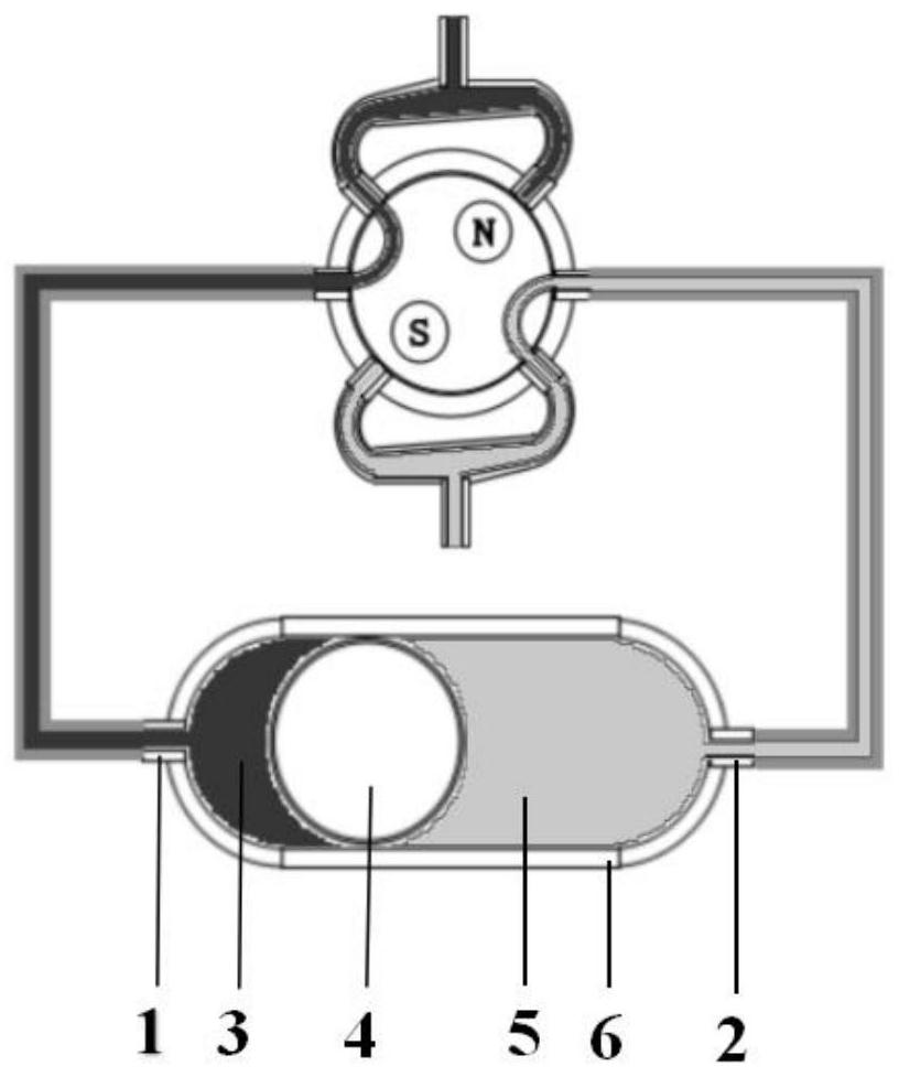
[0038] Such as figure 1 As shown, the shunt system of the present invention includes a cerebrospinal fluid shunt valve, a fluid inlet tube from the ventricle or lumbar cistern to the cerebrospinal fluid shunt valve, a fluid outlet tube from the cerebrospinal fluid shunt valve to the peritoneal cavity, and a body surface control device. The cerebrospinal fluid diversion valve includes a capsule-shaped cavity structure and a magnetic induction valve part.

[0039] The body surface control device includes a body surface external induction control card and a data recording processor.

[0040] The cerebrospinal fluid shunt valve is placed in the subcutaneous tissue of the subclavian region or the subcutaneous axillary line of the waist, and is parallel to the skin surface.

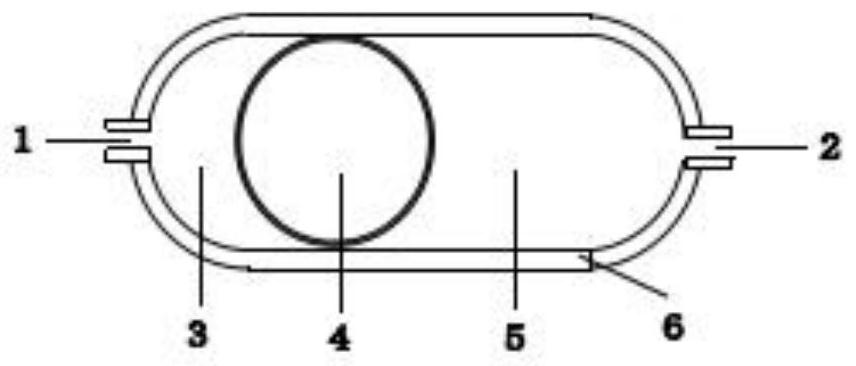
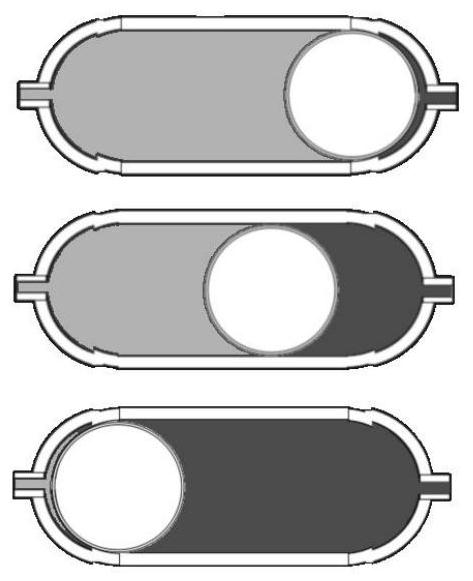
[0041] Such as figure 2 As shown, the inner side of the capsule-shaped cavity structure is smooth, and the inner side wall of the base is set with a mirror surface. The opaque hollow spherical piston 4 is di...


PUM


Abstract

The invention discloses a quantitative cerebrospinal fluid diversion system and method. The quantitative cerebrospinal fluid diversion system comprises a cerebrospinal fluid diversion valve, a fluid inlet pipe from ventricle or lumbar cistern to the cerebrospinal fluid diversion valve, a fluid outlet pipe from the cerebrospinal fluid diversion valve to an abdominal cavity and a body surface control device. The cerebrospinal fluid diversion valve comprises a cavity and a magnetic induction valve, wherein the cavity is divided into two side cavities by a piston, and the two sides of the cavity are connected with the fluid inlet pipe and the fluid outlet pipe through the magnetic induction valve. A piston horizontally moves in the cavity under the hydraulic pressure difference; an electromagnetic field controls the rotation angle of the magnetic induction valve in different time phases, and then the fluid inlet pipe and the fluid outlet pipe are switched and connected. A body surface external induction control card obtains the time from the opening time point to the filling time point of the cavity connected with one side of the fluid inlet pipe, calculates the time needed by one-timequantitative diversion, obtains the diversion speed and accordingly calibrates the upstream and downstream hydraulic pressure difference of the cavity. The ventricular system pressure value of a patient is calculated to judge whether the ventricular system pressure is in a normal range or not, so that siphon, excessive shunt and cerebrospinal fluid reflux are avoided.

Description

technical field [0001] The invention relates to a neurosurgery cerebrospinal fluid shunting system, in particular to a cerebrospinal fluid quantitative shunting system and a shunting method. Background technique [0002] In the neurosurgery treatment of communicating and non-communicating hydrocephalus, in addition to the use of drugs to reduce cerebrospinal fluid secretion, third ventriculostomy, endplate fistula, and third ventricle aqueduct reshaping, the most common treatment is ventricle- Peritoneal shunt and lumbar-peritoneal shunt shunt the redundant cerebrospinal fluid in the ventricular system, reduce the volume of cerebrospinal fluid in the ventricular system, thereby reducing the pressure of the ventricular system and improving the symptoms of intracranial hypertension in patients. [0003] However, the current ventricular-peritoneal shunt and lumbar-peritoneal shunt systems have the following disadvantages: [0004] (1) The current shunt system is divided into t...

Claims


Application Information

Patent Timeline
IPC IPC(8): A61M27/00G08C17/02G08C23/04A61M39/22F16K31/06F16K11/087
CPCA61M27/006G08C17/02G08C23/04A61M39/22F16K31/0603F16K31/0675F16K11/087A61M2027/004A61M2205/33A61M2205/3334
Inventor 李宽正
Owner 兴化市人民医院
Why Eureka
Try Eureka