
A kind of silicon wafer double-sided grinding equipment and its production process

A technology for double-sided grinding and silicon wafers, which is applied in grinding/polishing equipment, metal processing equipment, grinding/polishing safety devices, etc., which can solve the problem of poor quality of silicon wafers, inability to remove grinding impurities in time, and low yield. and other problems to achieve the effect of ingenious structural design

Active Publication Date: 2021-07-27
ZHEJIANG COWIN ELECTRONICS
View PDF7 Cites 0 Cited by
  • Summary
  • Abstract
  • Description
  • Claims
  • Application Information

AI Technical Summary

Problems solved by technology

[0005] In view of the above problems, the present invention provides a double-sided grinding equipment for silicon wafers and its production process. By setting the spraying and sweeping debris removal system on the upper grinding disc system, when the upper planetary disc mechanism revolves above the corresponding lower planetary disc The liquid is triggered, and the cleaning liquid is sprayed in the shape of a shower under the centrifugal action of the upper planetary disc mechanism, and the grinding impurities are sprayed from the center of the lower planetary disc to the outer ring and cleaned, and then cooperate with the exhaust system set on the lower grinding disc system. The chip extrusion system extrudes and transfers the mixed liquid of impurities, filters and recycles it. While automatically supplying liquid, the grinding impurities can be removed synchronously and in time through ingenious design of the liquid outlet method, which solves the problem that the grinding impurities in the prior art cannot be removed in time, The technical problems of poor quality and low yield of finished silicon wafers

Method used


Image

  • A kind of silicon wafer double-sided grinding equipment and its production process
  • A kind of silicon wafer double-sided grinding equipment and its production process
  • A kind of silicon wafer double-sided grinding equipment and its production process

Examples


Embodiment 1

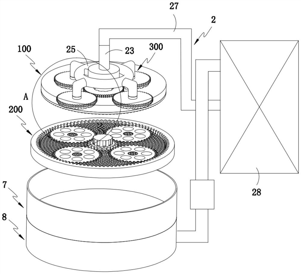
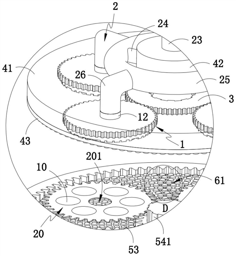
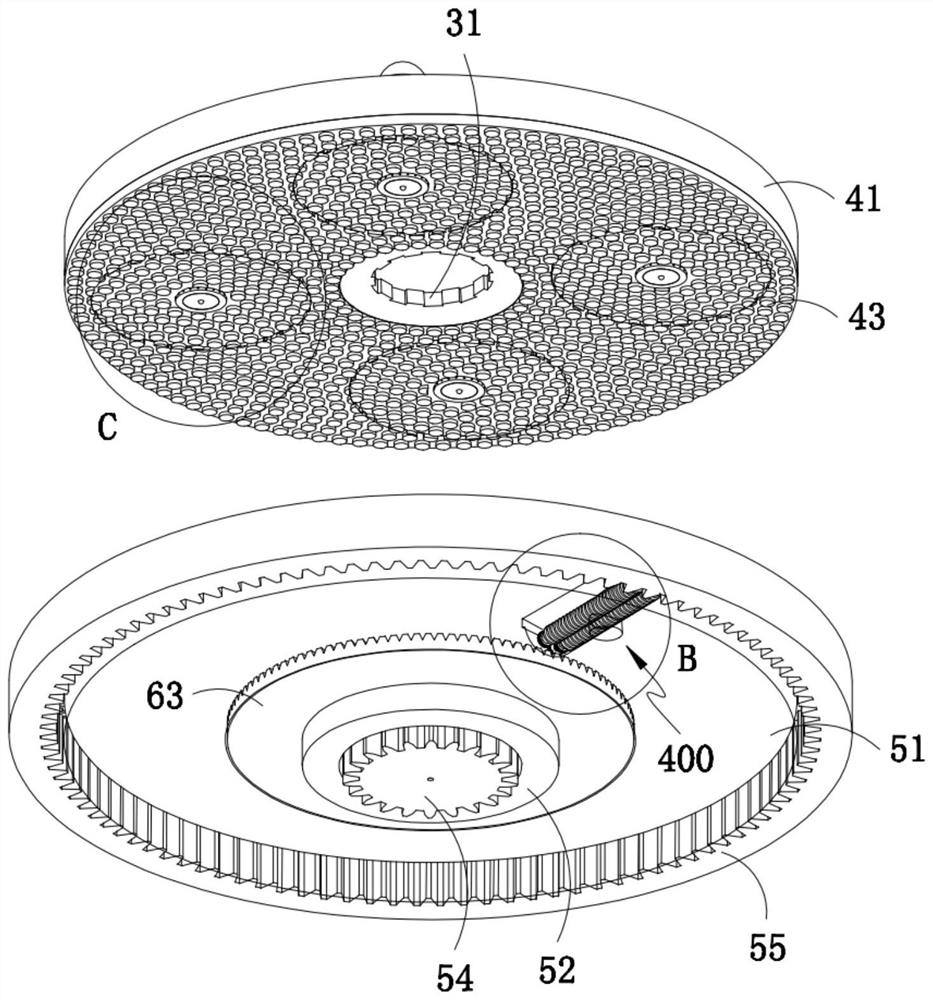
[0049] Such as Figure 1-2 As shown, a double-sided grinding device for silicon wafers includes an upper grinding disc system 100, a lower grinding disc system 200 that rotates in the opposite direction relative to the upper grinding disc system 100, and several loading silicon wafers 10 to be ground and placed on the grinding disc system 100. The lower planetary disc 20 that performs planetary motion between the upper grinding disc system 100 and the lower grinding disc system 200 also includes a spraying and sweeping debris removal system 300 arranged on the upper grinding disc system 100, and the spraying and sweeping debris removal system 300 includes Several upper planetary disc mechanisms 1 corresponding to the lower planetary disc 20, a liquid supply device 2 communicated with the upper planetary disc mechanism 1, and an upper transmission assembly 3 that drives the upper planetary disc mechanism 1 to rotate;

[0050] When the upper planetary disc mechanism 1 rotates ab...

Embodiment 2

[0084] For the sake of brevity, only the difference between Embodiment 2 and Embodiment 1 is described below; the difference between Embodiment 2 and Embodiment 1 is:

[0085] Further, such as Figure 8 As shown, the inner diameter r of the lower end of the outlet pipe body 121 at the nozzle 122 is smaller than the inner diameter R of the upper end;

[0086] In this embodiment, the inner diameter r at the nozzle 122 at the lower end of the water outlet pipe body 121 is set to be smaller than the inner diameter R at the upper end, so that when the valve opening groove 201 descends to open the nozzle 122, the hydraulic pressure at the nozzle 122 increases suddenly, so that The cleaning liquid 21 can be sprayed under high pressure, and the flushing intensity is high. In addition, the nozzle 122 is arranged to be inclined downward, so that the cleaning liquid 21 is sprayed at a certain angle with the surface of the lower planetary disc 20, and the flushing effect is better.

Embodiment 3

[0088] For the sake of simplicity, only the difference between Embodiment 2 and Embodiment 1 is described below; the difference between Embodiment 3 and Embodiment 1 is:

[0089] A kind of double-sided grinding production process of silicon wafer, such as Figure 11 shown, including the following steps:

[0090] Step 1, rotary grinding: take 4 to 5 lower planetary discs 20 and install them on the lower grinding disc system 200, put the silicon wafers 10 to be processed into the inner holes of the lower planetary discs 20 in sequence, and lower the upper grinding disc system 100 and apply pressure to start the grinding process;

[0091] In this embodiment, the grinding unit pressure is set at 1-2 N / cm2, the flow rate of pure water is set at 200-300 ml / min, and the rotation speed of the lower grinding disc is set at 40-50 rpm.

[0092] Step 2: Spray and remove debris: when the upper planetary disc mechanism 1 rotates above the lower planetary disc 20 and its top bead 124 falls...


PUM


Abstract

The invention provides a silicon wafer double-sided grinding equipment and its production process, including an upper and lower grinding disc system, a lower planetary disc loaded with silicon wafers to be ground, and a spraying and sweeping debris removal system arranged on the upper grinding disc system. The debris removal system includes an upper planetary disk mechanism corresponding to the lower planetary disk, a liquid supply device connected to the upper planetary disk mechanism, and an upper transmission assembly that drives the upper planetary disk mechanism to rotate. The upper planetary disk mechanism revolves to the corresponding lower planetary disk. When it is above, the liquid is triggered, and the cleaning liquid is sprayed in the shape of a shower under the action of rotation and centrifugation, and the grinding impurities are sprayed and cleaned from the center of the lower planetary disc to the outer ring, and then cooperate with the chip removal set on the lower grinding disc system to extrude The system squeezes out the impurity mixed liquid, transfers it, filters it and recycles it. While supplying the liquid automatically, the grinding impurities can be removed synchronously and in time through ingenious design of the liquid outlet method, which solves the problem that the grinding impurities in the prior art cannot be removed in time and the silicon wafer is finished. Technical problems of poor quality and low yield.

Description

technical field [0001] The invention relates to the field of silicon wafer grinding, in particular to a silicon wafer double-sided grinding equipment and a production process thereof. Background technique [0002] Monocrystalline silicon has become the most widely used semiconductor material in integrated circuit manufacturing. More than 95% of semiconductor devices and more than 99% of integrated circuits in the world use single crystal silicon as the substrate material. In the process of preparing silicon wafers, the surface of single crystal silicon wafers needs to be ground and polished. Both sides are ground simultaneously. Through the upper and lower grinding discs, the center wheel, and the planetary wheel, the four directions and speeds of the grinding movement are coordinated during processing, so as to achieve the efficient operation of simultaneous grinding of the upper and lower surfaces. [0003] The Chinese invention patent with the application number CN20182...

Claims


Application Information

Patent Timeline
Patent Type & Authority Patents(China)
IPC IPC(8): B24B37/08B24B37/34B24B55/06B24B55/12B24B37/28
CPCB24B37/08B24B37/28B24B37/34B24B55/06B24B55/12
Inventor 吴晓峰郭兵健何国君刘小磐
Owner ZHEJIANG COWIN ELECTRONICS
Learn More