
Gearbox

A gearbox and housing technology, applied in the field of gearboxes, can solve the problems such as the offset of the driven gear of the spiral umbrella, affecting the transmission efficiency, large noise, etc., and achieve the effects of reducing gear wear, reliable power transmission, and ensuring transmission efficiency.

Pending Publication Date: 2020-10-13
ZHEJIANG JINDAO TECH CO LTD
View PDF1 Cites 0 Cited by
  • Summary
  • Abstract
  • Description
  • Claims
  • Application Information

AI Technical Summary

Problems solved by technology

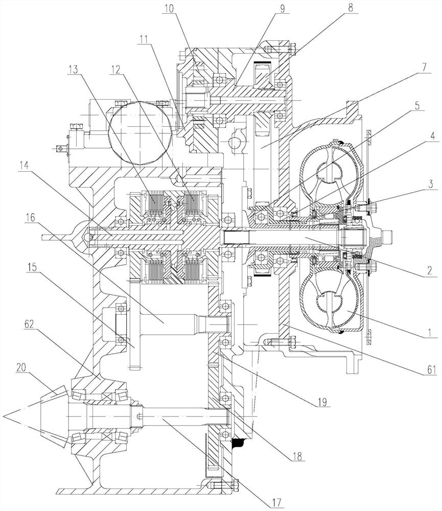
[0004] In this scheme, the intermediate shaft and the intermediate gear are arranged in the gearbox housing, and the power of the first gear fixed to the pump hub is transmitted to the driven gear of the oil pump, thereby causing the PTO shaft to rotate, so as to realize the power transmission of the PTO, but the technology in the art In the process of use, personnel found that the above invention still has the following technical problems: The way of setting the intermediate shaft and the intermediate gear in the housing makes the internal structure of the gearbox slightly complicated, which increases the processing difficulty and manufacturing cost, and multiple sets of gears mesh The transmission makes a lot of noise
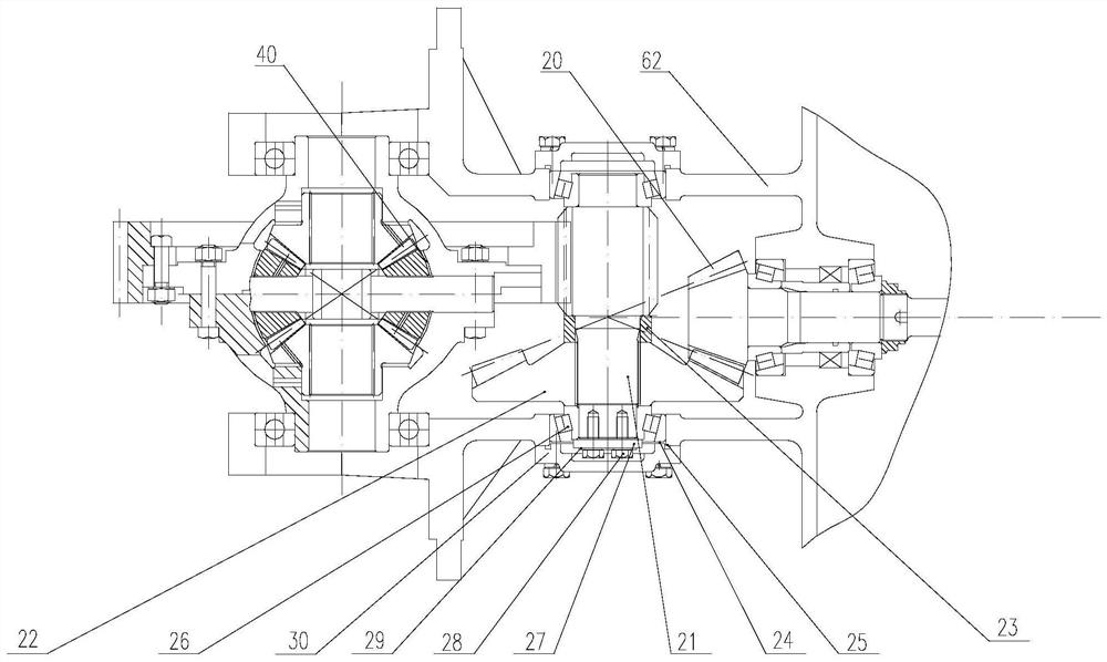
[0005] In addition, the transmission between the transmission output shaft and the differential assembly generally adopts the gear shaft and the spiral bevel driven gear on the gear shaft. The spiral bevel driven gear here is generally connected to the gear shaft through splines. Installation, this will make the spiral bevel driven gear axially offset on the gear shaft after long-term use, which will affect the transmission efficiency, and the spiral bevel driven gear adopts a bowl-shaped structure design, so that it will The amount of deformation is difficult to control, and the transmission noise remains high; in the existing structure, the theoretical installation distance and meshing backlash of the spiral bevel driven gear are difficult to adjust and calibrate

Method used


Image

  • Gearbox
  • Gearbox

Examples


Embodiment Construction

[0025] It should be pointed out that the following detailed description is exemplary and intended to provide further explanation to the present application. Unless defined otherwise, all technical and scientific terms used herein have the same meaning as commonly understood by one of ordinary skill in the art to which this application belongs.

[0026] It should be noted that the terminology used here is only for describing specific implementations, and is not intended to limit the exemplary implementations according to the present application. As used herein, unless the context clearly dictates otherwise, the singular is intended to include the plural, and it should also be understood that when the terms "comprising" and / or "comprising" are used in this specification, they mean There are features, steps, operations, means, components and / or combinations thereof.

[0027] Furthermore, in describing the present invention, it is to be understood that the terms "center", "longit...


PUM


Abstract

The invention relates to a gearbox. The gearbox comprises a first shell, a second shell, a torque converter assembly, a PTO assembly transmission assembly, a differential assembly, an input shaft, anidler shaft, an output shaft and a gear assembly; the torque converter assembly comprises a hydraulic torque converter, a pump hub and a driving chain wheel, wherein the driving chain wheel is in transmission connection with the pump hub; the PTO assembly comprises a guide wheel seat, a PTO shaft and a chain, wherein the guide wheel seat is fixedly connected with the first shell, the driving chainwheel is installed on the guide wheel seat, and the driving chain wheel is in transmission fit with the PTO shaft through the chain; and the gear assembly comprises a gear shaft and a spiral bevel driven gear, wherein the gear shaft is sleeved with the spiral bevel driven gear, a lining is further arranged between the spiral bevel driven gear and a meshing tooth part in a sleeved mode, and the other side of the spiral bevel driven gear abuts against a first bearing. According to the gearbox, the PTO output function is achieved through chain transmission, and the structure is simplified; and the spiral bevel driven gear is fixed to the gear shaft, so that the noise is reduced, and the stability is improved.

Description

technical field [0001] The invention relates to the technical field of forklifts, in particular to a gearbox. Background technique [0002] Due to the smooth and comfortable characteristics of hydraulic drive, hydraulic drive has been more and more widely used in various types of machinery. Since the pressure of most mechanical hydraulic systems comes from the hydraulic pump, the driving mode of the hydraulic pump is divided into two modes: direct engine drive and vehicle pulley transmission. In small-tonnage forklifts, the direct drive of diesel engines is more widely used, so it is necessary to design a PTO output interface for driving hydraulic pumps on the diesel engine of small-tonnage forklifts to realize PTO power transmission. [0003] Therefore, the Chinese patent document whose publication number is CN111005999A discloses a gearbox, including a first housing, a second housing, a differential assembly, a shift assembly, a torque converter assembly and a PTO assembl...

Claims


Application Information

Patent Timeline
IPC IPC(8): F16H47/06F16H57/02F16H57/023F16H57/028F16H57/035F16H57/037
CPCF16H47/06F16H47/065F16H57/023F16H57/028F16H57/035F16H57/037F16H2057/02056F16H2057/02095
Inventor 陆立峰金刚强
Owner ZHEJIANG JINDAO TECH CO LTD
Learn More