Industrial flue gas desulfurization and denitrification dust remover

A technology for desulfurization and denitrification and industrial flue gas, which is applied in gas treatment, chemical instruments and methods, and dispersed particle filtration, etc. It can solve the problems of reduced dust removal effect, imperfect dust removal structure, and dust discharge into the atmosphere, so as to improve work efficiency, Guaranteed uninterrupted operation and convenient cleaning effect

Inactive Publication Date: 2020-10-16
沈春丰
View PDF4 Cites 3 Cited by
  • Summary
  • Abstract
  • Description
  • Claims
  • Application Information

AI Technical Summary

Problems solved by technology

[0003] Traditional industrial flue gas desulfurization and denitrification dust collectors focus on desulfurization and denitrification during actual use, resulting in imperfect dust removal structure, which easily causes a small amount of dust to follow the exhaust gas into the atmosphere, greatly reducing its dust removal effect. For this, it is necessary to design a Industrial flue gas desulfurization and denitrification dust collector

Method used


Image

  • Industrial flue gas desulfurization and denitrification dust remover
  • Industrial flue gas desulfurization and denitrification dust remover
  • Industrial flue gas desulfurization and denitrification dust remover

Examples


Embodiment Construction

[0025] In order to make the technical means, creative features, goals and effects achieved by the present invention easy to understand, the present invention will be further described below in conjunction with specific embodiments.

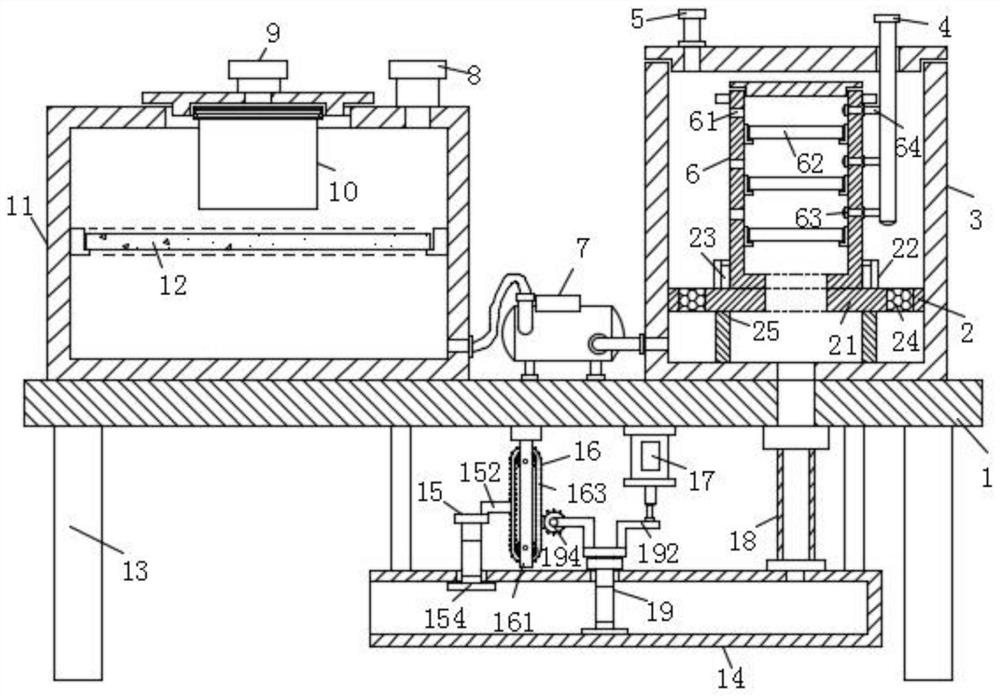
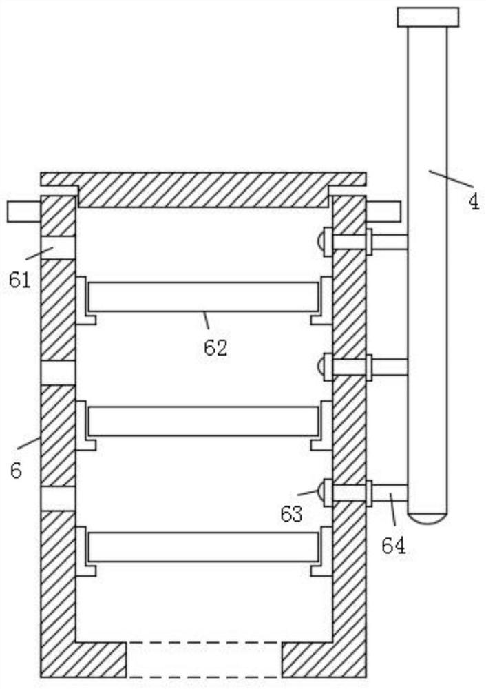
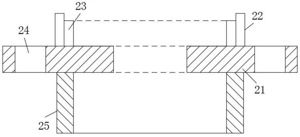
[0026] Such as Figure 1-Figure 7 As shown, an industrial flue gas desulfurization and denitrification dust remover according to the present invention includes a platen 1, a desulfurization barrel 3 is fixedly installed on the top of the platen 1, a built-in bracket 2 is fixedly installed in the desulfurization barrel 3, and the built-in bracket The top of the desulfurization bucket 3 is fitted with a built-in filter cartridge 6, and the top of the desulfurization bucket 3 is fixedly equipped with an oxygen discharge pipe 5. Water inlet pipe 4, and the water inlet pipe 4 is connected with the built-in filter cartridge 6, the top of the platen 1 is fixedly installed with a denitration box 11, and the top of the denitration box 11 is fixedly install...


PUM


Abstract

The invention relates to the field of industrial flue gas dust removal, in particular to an industrial flue gas desulfurization and denitrification dust remover. The dust remover includes a table plate, a desulfurization barrel is fixedly mounted at the top end of the table plate; a built-in bracket is fixedly mounted in the desulfurization barrel; a built-in filter cartridge is mounted at the topend of the built-in bracket in a clamping manner; an oxygen inlet pipe is fixedly mounted at the top end of the desulfurization barrel; a water inlet pipe is inserted into the desulfurization barrel;a denitration box is fixedly mounted at the top end of the table plate; a filter screen cover is mounted on the lower surface of a top cover of the denitration box through threads; a filter plate ismounted in the denitration box in a clamping manner; an air pump is fixedly mounted at the top end of the platen; a discharge pipeline is fixedly suspended at the bottom end of the bedplate; a first dust filtering mechanism and a second dust filtering mechanism are movably mounted on the discharge pipeline; the air cylinder is fixedly installed on the lower surface of the table plate, the transmission mechanism is installed at the bottom end of the table plate, the filter screen cover, the activated carbon plate, the first dust filtering mechanism and the second dust filtering mechanism are arranged, dust can be treated in an interception and adsorption combined mode, and the dust removal effect of the dust removal device is greatly improved.

Description

technical field [0001] The invention relates to the field of industrial flue gas dedusting, in particular to an industrial flue gas desulfurization and denitrification dust remover. Background technique [0002] Industrial flue gas refers to the waste smoke and gas generated in industrial production. Since industrial flue gas contains a large amount of harmful substances such as sulfur dioxide, it is easy to pollute the environment. When industrial flue gas is discharged, it needs to be desulfurized and denitrified to reduce The content of harmful substances in the exhaust gas, and the dust in the flue gas needs to be treated, which plays an important role in environmental protection. Therefore, when the industrial flue gas is discharged, a desulfurization, denitrification and dust collector must be used to filter the flue gas, and After meeting the emission standards, the exhaust gas can be discharged into the atmosphere. [0003] Traditional industrial flue gas desulfuriz...

Claims


Application Information

Patent Timeline
Patent Type & Authority Applications(China)
IPC IPC(8): B01D46/12B01D46/00B01D53/00
CPCB01D46/0036B01D46/12B01D53/00B01D2253/102B01D2258/0283
Inventor 沈春丰赵光宇
Owner 沈春丰
Why Eureka
Try Eureka