Spatial positioning and attitude navigation of assembly tool by using machine vision

An assembly tool and machine vision technology, applied in the field of visual measurement technology and intelligent assembly, can solve problems such as inconvenient use, affecting measurement accuracy, and inability to meet wireless positioning of wireless assembly tools, and achieve the effect of ensuring operational flexibility and light structure

Pending Publication Date: 2020-10-16
菲烁易维(重庆)科技有限公司
View PDF0 Cites 9 Cited by
  • Summary
  • Abstract
  • Description
  • Claims
  • Application Information

AI Technical Summary

Problems solved by technology

Among them, the manipulator navigation method is to fix the assembly tool on the positioning manipulator with an angle encoder, and calculate the spatial position and attitude of the assembly tool through the angle of the angle encoder and the length of the manipulator or the length of the rope. There are many problems in this method: (1) It cannot meet the requirements of wireless positioning of wireless assembly tools; (2) It can only be used by mechanical clamping, which is very easy to interfere with the workpiece and surrounding objects; (3) Poor flexibility and convenience; ( 4) The response time is long, and the measurement and positioning accuracy is not good
There are the following problems in the visual navigation method of LED sign points by actively emitting light: (1) The LEDs that are actively emitting light need to be powered, and if an external power supply is used, the cable will interfere with the operation; Affect the measurement accuracy; (2) Due to the high frequency of use and the limited battery power supply time, the battery needs t

Method used


Image

  • Spatial positioning and attitude navigation of assembly tool by using machine vision
  • Spatial positioning and attitude navigation of assembly tool by using machine vision
  • Spatial positioning and attitude navigation of assembly tool by using machine vision

Examples


Embodiment

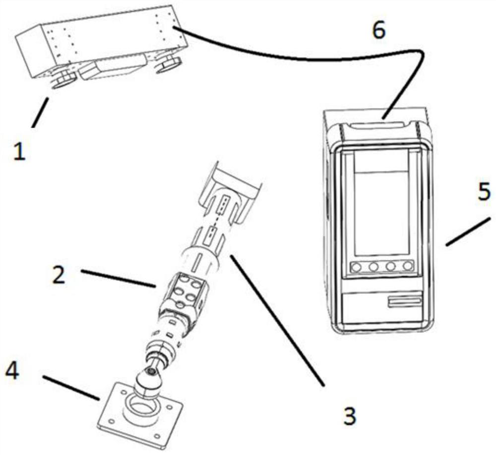
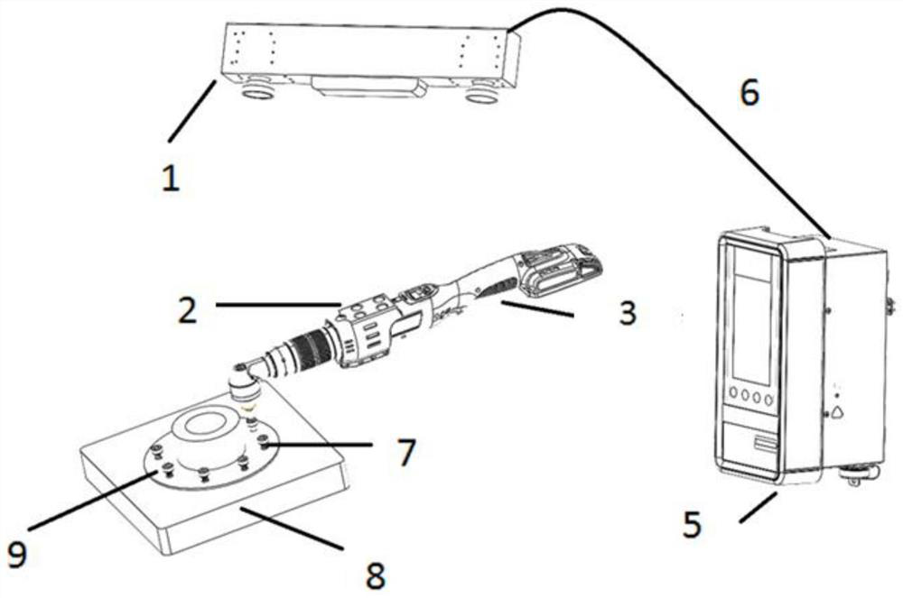
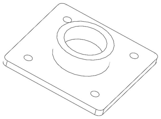
[0040] Such as figure 1 , figure 2 and image 3 As shown, the system used for space positioning and attitude navigation of assembly tools using machine vision includes: assembly tool control system 5 connected to monocular or binocular vision 3D measurement host 1 through wireless or wired communication 6, passive reflective marking device 2 set On the assembly tool 3, the passive reflective marking point device 2 is provided with a plurality of passive reflective marking points. A passive reflective marker point device 2, a monocular or binocular vision three-dimensional measurement host 1 outputs the results to the control system 5 of the assembly tool in real time through various wireless and wired communication protocols; Calibration, the calibration plate 4 is provided with a connection port, the axis of the connection port coincides with the axis of the output end of the assembly tool 3, and the end faces are in close contact. The connection port is used to closely co...


PUM


Abstract

The invention provides a method for spatial positioning and attitude navigation of an assembly tool by using machine vision. The method comprises the following steps: establishing a coordinate relationship between an output end of the assembly tool and a mark point device; acquiring an image of the marking point device on a camera coordinate system, and calculating a space attitude of the markingpoint device under the camera coordinate system and a position and an attitude of an output end of the assembling tool under the camera coordinate system; teaching, wherein corresponding position andposture data of the whole process from starting to finishing of operation are obtained; in the working process of the assembly system, obtaining the spatial position and attitude data of the assemblytool in real time, and comparing the spatial position and attitude data with the teaching position and attitude data. The brand-new method is provided for assembling tool spatial positioning and attitude navigation, and high-precision spatial positioning of the assembling tool is achieved.

Description

technical field [0001] The invention belongs to the field of visual measurement technology and intelligent assembly, and in particular relates to a method for spatial positioning and posture navigation of assembly tools by using machine vision. Background technique [0002] In industrial intelligent production, it is necessary to measure the spatial position and attitude of assembly tools (such as electric wrench) for process control, such as: tightening the engine block or riveting structural parts. On the one hand, it is necessary to ensure a certain order Assembly (such as diagonal assembly or specified sequence assembly), on the other hand, it is necessary to ensure that the tightening torque or tensile force of each connecting piece meets the requirements, and there is no wrong assembly or missing assembly. It is best to be able to guide the operator to the specified precision. position to start assembly. [0003] In the prior art, there are a robotic arm navigation me...

Claims


Application Information

Patent Timeline
IPC IPC(8): G05B19/19G01B11/00G01C1/00G01C11/00G01C21/00B23P19/06
CPCB23P19/06G01B11/002G01C1/00G01C11/00G01C21/00G05B19/19G05B2219/35349
Inventor 游四清黄科游晓龙白灵黄菊芳孔俊陈平平
Owner 菲烁易维(重庆)科技有限公司
Why Eureka
Try Eureka