Supercharge Your Innovation With Domain-Expert AI Agents!

Method of outputting UVW signals in incremental encoder IC

An incremental encoder and incremental signal technology, which is applied in the direction of converting sensor output, instruments, measuring devices, etc., can solve the problem of large noise, the inability of the incremental encoder to output the absolute position information of the displacement change, and the inability to determine the motor Control the sequence and direction of coil energization, etc.

Pending Publication Date: 2020-10-20
赛卓微电子(深圳)有限公司
View PDF8 Cites 0 Cited by
  • Summary
  • Abstract
  • Description
  • Claims
  • Application Information

AI Technical Summary

Problems solved by technology

[0004] Since the incremental encoder cannot output the absolute position information of the displacement change, at the start time, the brushless motor using the incremental encoder cannot determine the order and direction of the motor control coil energization
At this time, the usual method is to use the method of traversing the energization sequence and trying many times to find the correct sequence of coil energization. At this time, the motor will vibrate back and forth at a small angle, resulting in large noise.

Method used


Image

  • Method of outputting UVW signals in incremental encoder IC
  • Method of outputting UVW signals in incremental encoder IC
  • Method of outputting UVW signals in incremental encoder IC

Examples


Embodiment 1

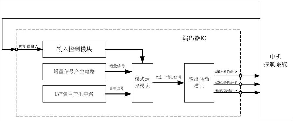
[0041] A method for outputting UVW signals in an incremental encoder IC, refer to figure 1 It is a block diagram of a method for outputting UVW signals in an incremental encoder IC, including the following input and output and circuit modules:

[0042] The input control module is used to accept the UVW signal request sent by the control terminal (motor control system). It needs to be pointed out that the input control is not necessary in the actual solution.

[0043] The mode selection module is used to select the incremental output mode or the UVW signal output; wherein, the incremental A, B, and Z signal outputs are generated through the incremental signal generation circuit; U, V, and W signals are generated through the UVW signal generation circuit.

[0044] The output drive module DRV1 is used to send the output position signal.

Embodiment 2

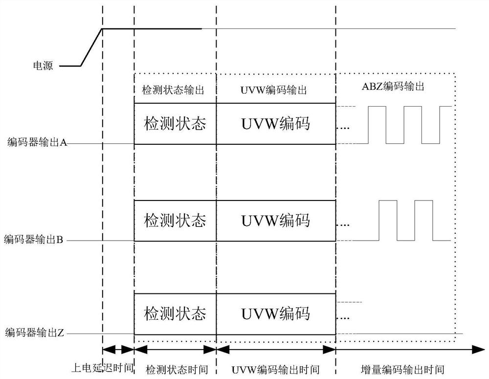
[0046] A method for outputting UVW signals in an incremental encoder IC, using a multiplexed UVW signal output mode, refer to figure 2As shown, after the encoder is powered on, after an appropriate time delay, the ABZ encoding state is detected, the input control module sets the mode selection module to output UVW encoding output mode, and connects the output of the UVW signal generation circuit to the output drive module; after UVW After the encoding output time, the input control module sets the mode selection module to the incremental encoding output mode, and connects the output of the incremental signal generating circuit to the output driving module to form an ABZ encoding output, and the incremental encoder works normally.

Embodiment 3

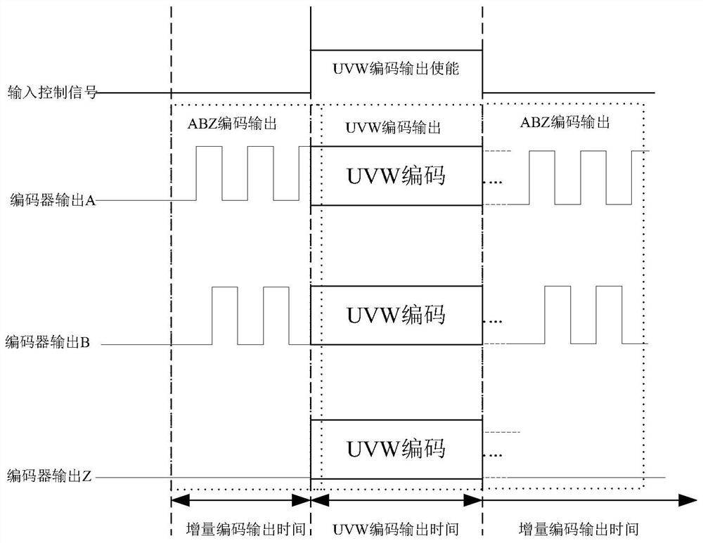
[0048] A method for outputting UVW signals in an incremental encoder IC, using a multiplexed UVW signal output mode, refer to figure 2 As shown, after the encoder is powered on, after an appropriate time delay, the ABZ encoding state is detected, the input control module sets the mode selection module to output UVW encoding output mode, and connects the output of the UVW signal generation circuit to the output drive module; after UVW After the encoding output time, the input control module sets the mode selection module to the incremental encoding output mode, and connects the output of the incremental signal generating circuit to the output drive module to form an ABZ encoding output, and the incremental encoder works normally;

[0049] refer to image 3 As shown, after the control terminal (motor control system) sends a request, the input control module sets the mode selection module to the output UVW code output mode, and connects the output of the UVW signal generation ci...


PUM


Abstract

The invention discloses a method for outputting UVW signals in an incremental encoder IC. An incremental encoder IC which can output U, V and W signals at the same time is included, and the encoder iscomposed of an incremental signal generation module, a UVW signal generation module, an input control module, a mode selection module and an output driving module. The input control module is used for configuring mode selection and driving increment signal or UVW signal output by judging the motor state and signal feedback. According to the method for outputting the UVW signals in the incrementalencoder IC, the U, V and W signals are output by multiplexing the output interface of the incremental encoder, and a brushless motor system determines the sequence and direction of energization of amotor control coil during initial energization. Therefore, the compatibility of the incremental encoder is improved, and the jitter and the noise during the starting of the motor are greatly reduced at the same time. The method can be applied to the fields of motor control, motor sensing and the like.

Description

technical field [0001] The invention relates to the technical field of electronic circuits, in particular to a method for outputting UVW signals in an incremental encoder IC. Background technique [0002] Incremental encoder converts the displacement change into a periodic electrical signal, and then converts the electrical signal into a counting pulse, and uses the number of pulses to represent the magnitude of the displacement. Incremental encoders usually have three signal outputs (there are six differential signals): A, B, and Z. The signals of the two channels A and B are generally orthogonal (that is, 90° mutual difference) pulse signals. The signals of A and B phases differ by 90 degrees, and the forward rotation and reverse rotation of the encoder can be judged by judging whether A phase is in front or B phase, and Z phase represents the zero reference position. The advantage of the incremental encoder is that the principle is simple and the structure is simple, the...

Claims


Application Information

Patent Timeline
IPC IPC(8): G01D5/245G01D5/249H02P6/08H02P6/16
CPCG01D5/2451G01D5/249H02P6/08H02P6/16
Inventor 张超汪坚雄胡枭
Owner 赛卓微电子(深圳)有限公司
Features
  • R&D
  • Intellectual Property
  • Life Sciences
  • Materials
  • Tech Scout
  • Unparalleled Data Quality
  • Higher Quality Content
  • 60% Fewer Hallucinations
Learn More