
A Bias Control Circuit System of Electro-optic Modulator with High Locking Precision

An electro-optical modulator and circuit system technology, applied in general control systems, control/regulation systems, program control, etc., can solve problems such as slow response time, low control accuracy, and insensitivity to changes, and improve control accuracy and processing speed. , Improve the effect of system locking accuracy

Active Publication Date: 2022-03-04
CHINA ELECTRONIC TECH GRP CORP NO 38 RES INST
View PDF7 Cites 0 Cited by
  • Summary
  • Abstract
  • Description
  • Claims
  • Application Information

AI Technical Summary

Problems solved by technology

[0005] The technical problem to be solved by the present invention is: how to solve the problems of low control precision, slow response time and insensitivity to changes in the external environment (temperature, stress, etc.) Electro-optic modulator bias control circuit system with high locking precision

Method used


Image

  • A Bias Control Circuit System of Electro-optic Modulator with High Locking Precision
  • A Bias Control Circuit System of Electro-optic Modulator with High Locking Precision
  • A Bias Control Circuit System of Electro-optic Modulator with High Locking Precision

Examples


Embodiment Construction

[0026] The embodiments of the present invention are described in detail below. This embodiment is implemented on the premise of the technical solution of the present invention, and detailed implementation methods and specific operating procedures are provided, but the protection scope of the present invention is not limited to the following implementation example.

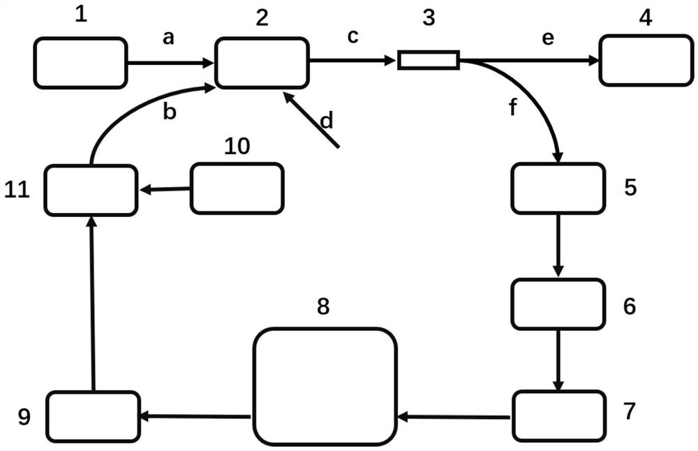
[0027] Such as figure 1 As shown, this embodiment provides a technical solution: an electro-optic modulator bias control circuit system with high locking accuracy, including a laser module 1, an electro-optic modulator 2, a fiber beam splitter 3, a high-frequency photodetector 4, Low-frequency photodetector 5 , signal conditioning module 6 , ADC and operating point setting module 7 , MCU control module 8 , DAC module 9 , pilot generation module 10 , and signal mixing module 11 .

[0028] The optical output end of the laser 1 is connected to the a port of the electro-optic modulator 2, the d port of the electro-opt...


PUM


Abstract

The invention discloses an electro-optic modulator bias control circuit system with high locking precision, belonging to the technical field of Mach-Zehnder modulator operating point control, including a laser module, an electro-optic modulator, an optical fiber beam splitter, and a high-frequency photoelectric detection device, low-frequency photodetector, signal conditioning module, ADC and operating point setting module, MCU control module, DAC module, pilot frequency generation module, and signal mixing module. The present invention adds a 1KHz tiny perturbation signal to the input end of the electro-optic modulator, and processes the optical signal and the pilot signal contained therein separately after being detected by a low-frequency photoelectric detector, respectively improving the measurement accuracy of the two signals; and using The successive approximation method and the FFT algorithm have greatly improved the control accuracy and processing speed of the feedback signal; the PID algorithm is also used to control the ratio K of the amplitude of the DC signal output by the low-frequency detector to the AC signal, which improves the system Locking precision.

Description

technical field [0001] The invention relates to the technical field of operating point control of a Mach-Zehnder modulator with external intensity modulation, in particular to an electro-optical modulator bias control circuit system with high locking precision. Background technique [0002] With the rapid development of Internet business forms and the explosive growth of data volume, users of communication equipment have put forward higher requirements for network bandwidth and portability. Wireless communication is favored by more and more users because of its advantages of portability and flexibility. However, as the demand for data transmission speed continues to increase, broadband wireless communication technology has become a focus of attention, making the two disciplines that were originally parallel to each other gradually merged. , became microwave photonics. [0003] Microwave photonics technology combines the large capacity of optical network and the flexibility ...

Claims


Application Information

Patent Timeline
Patent Type & Authority Patents(China)
IPC IPC(8): G05B19/042
CPCG05B19/0423G05B2219/24215
Inventor 陈曦邹志勇周中昊
Owner CHINA ELECTRONIC TECH GRP CORP NO 38 RES INST
Learn More