
Self-suction semi-permeable membrane drainage network and implementation method thereof

An implementation method, semi-permeable membrane technology, applied in chemical instruments and methods, water/sludge/sewage treatment, sludge treatment, etc.

Active Publication Date: 2020-10-23
HOHAI UNIV
View PDF3 Cites 1 Cited by
  • Summary
  • Abstract
  • Description
  • Claims
  • Application Information

AI Technical Summary

Problems solved by technology

[0005] The invention provides a self-priming semi-permeable membrane drainage network and its implementation method, which solves the technical problem of rapid water reduction when the above-mentioned high-moisture content sludge is used as embankment backfill

Method used


Image

  • Self-suction semi-permeable membrane drainage network and implementation method thereof
  • Self-suction semi-permeable membrane drainage network and implementation method thereof
  • Self-suction semi-permeable membrane drainage network and implementation method thereof

Examples


Embodiment approach

[0035] This embodiment provides a method for implementing a self-priming semi-permeable membrane drainage network, including the following steps:

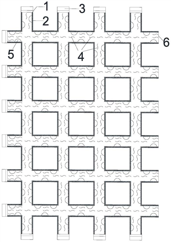
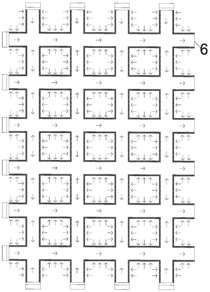
[0036] Step 1: Transport the solidified soil with high water content to the embankment filling place, fill half of the required height of the embankment, and then lay a self-priming semi-permeable membrane drainage network on the half-filled embankment 9 . Such as Figure 4 As shown, the top surface of the embankment 9 filled with half the height has a certain inclination, the liquid injection port 6 of the drainage net is located on the higher side, and the length of the PVC pipe 7 arranged laterally is greater than the width of the embankment 9, so The liquid injection port 6 exceeds the side of the embankment 9. In this embodiment, the inclination is 5-10°.

[0037] Step 2: Pour sulfurous acid pulp waste liquid 4 into the PVC pipe 7 of the drainage network through the liquid injection port 6 until the sulfurous acid pulp waste...

Embodiment 2

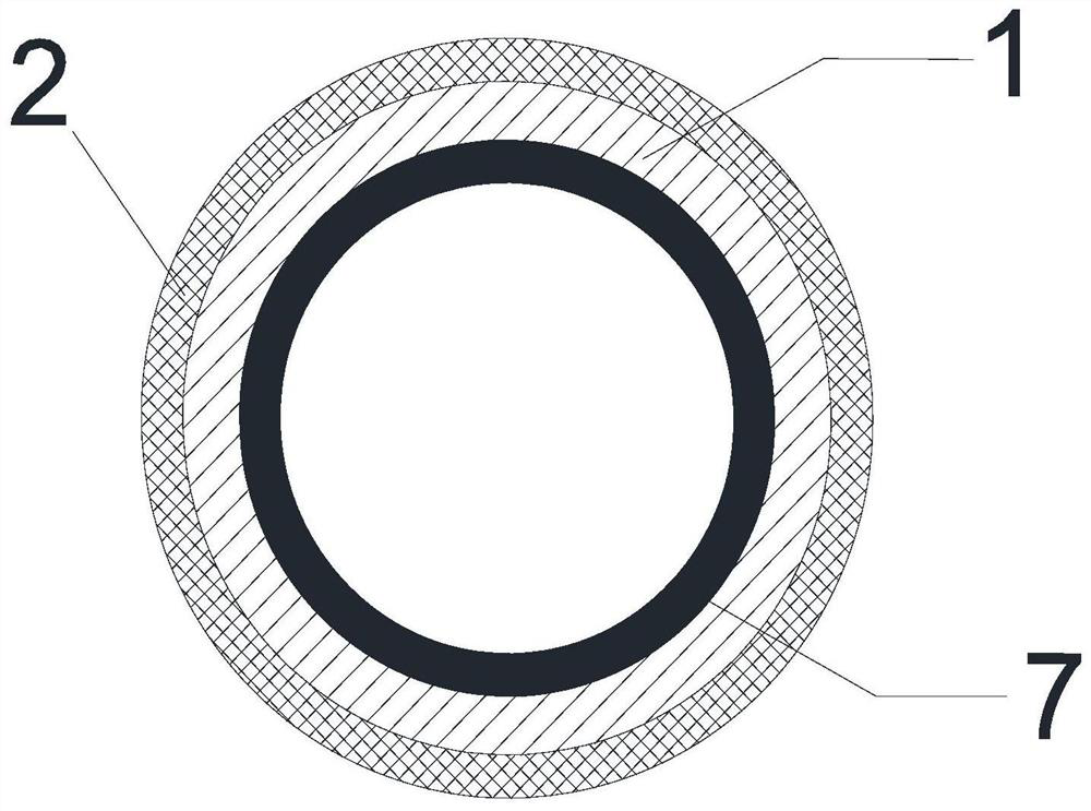
[0042] Step 1. Transport the solidified soil with high moisture content to the embankment filling place, fill half of the height first, and make a self-priming semi-permeable membrane drainage network. The length of the horizontal PVC pipe 7 of the self-priming semi-permeable membrane drainage network depends on the width of the embankment, and it is greater than the embankment 9 width 2m, and the length of the longitudinal PVC pipe 7 is 14m, and the diameter of the PVC pipe 7 is 5cm. On the wall, an electric drill is used to displace and open permeation holes 5 with a diameter of 3 cm, and the interval between the permeation holes 5 is 5 cm. The outside of the PVC pipe 7 is wrapped with a semi-permeable membrane 1 made of polyvinyl alcohol, and the outside of the semi-permeable membrane 1 is wrapped and fixed with barbed wire or a synthetic resin net.

[0043]Step 2. Laying a self-priming semi-permeable membrane drainage network on the embankment 9 filled with half the height...


PUM


Abstract

The invention discloses a self-suction semi-permeable membrane drainage network which comprises PVC pipes connected in a crisscross mode; the two ends of each longitudinally-arranged PVC pipe are sealed through pipe plugs respectively; one end of each transversely-arranged PVC pipe is sealed through a pipe plug, and the other end of the transversely-arranged PVC pipe is opened to serve as a liquidinjection opening; a plurality of permeation holes are formed in the PVC pipes, the outer side surfaces of the PVC pipes are coated with semi-permeable membranes, and a protective layer is arranged outside the semi-permeable membrane. The invention further discloses an implementation method of the self-suction semi-permeable membrane drainage network, water in soil penetrates through the semi-permeable membranes to enter the pipes to be discharged by means of the osmotic pressure of solutions inside and outside the PVC pipes, the PVC pipes drain water at the same time, the drainage area is enlarged, the drainage process is simple and efficient, manpower and material resources are saved, the drainage efficiency is high, and the increase of the foundation bearing capacity is effectively promoted. In addition, dust pollution is avoided in the rapid water reducing process, the used sulfite pulp waste liquid is non-toxic, high in viscosity and not prone to seeping out of the semi-permeablemembrane, good seepage pressure is achieved, and the environmental protection requirement is met.

Description

technical field [0001] The invention belongs to the technical field of civil engineering, and in particular relates to a self-priming semi-permeable membrane drainage net and an implementation method thereof. Background technique [0002] At present, one of the main ways of resource utilization of high water content silt excavated in engineering is to use it as embankment filler. Generally, the muddy soil is transformed into high-quality soil that meets the strength and deformation requirements of embankment filler by first reducing water and then solidifying. . One of the water reduction methods is air drying, which does not require much manpower and material resources, but completely relies on natural evaporation to reduce water, and is limited by weather conditions, the water reduction speed is slow and the efficiency is low, which seriously affects the later curing progress and construction process; In addition, the chemical water reduction method is used to achieve the...

Claims


Application Information

Patent Timeline
IPC IPC(8): C02F11/121
CPCC02F11/121
Inventor 陈永辉陈庚孔纲强陈龙冯兆祥高玉峰
Owner HOHAI UNIV
Learn More