
Cold-bend steel embedded double corrugated steel plate shear wall

A technology of steel plate shear wall and corrugated steel plate, which is applied in the direction of wall, building component, earthquake resistance, etc., can solve the problem of unfavorable wall energy consumption, weak wall continuity and integrity, and unfavorable promotion and application of cold-formed steel shear wall, etc. question

Active Publication Date: 2020-10-23
HUNAN UNIV
View PDF7 Cites 6 Cited by
  • Summary
  • Abstract
  • Description
  • Claims
  • Application Information

AI Technical Summary

Problems solved by technology

However, the steel plate shear wall has a large width-to-thickness ratio or height-to-thickness ratio, which makes the steel plate prone to out-of-plane buckling instability under the action of horizontal lateral force, which affects its bearing capacity; The adverse effects of the edge components will also lead to a serious pinch effect on the hysteretic curve of the steel plate shear wall, which is not conducive to the energy dissipation of the wall in the earthquake
When the steel plate buckles, a lot of noise is generated, which affects the user experience
In terms of wall modularization, most walls are connected and fixed by panels or angle steel at the corners. The continuity and integrity of the walls are weak. Under the action of lateral force, the corners are easily damaged.
Due to the above reasons, the traditional cold-formed steel shear wall is not conducive to the application in engineering

Method used


Image

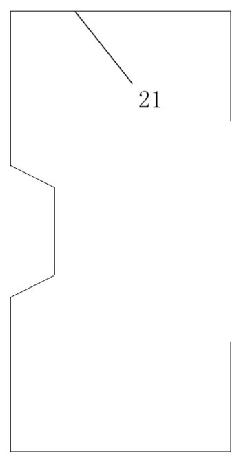
  • Cold-bend steel embedded double corrugated steel plate shear wall
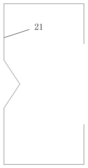
  • Cold-bend steel embedded double corrugated steel plate shear wall
  • Cold-bend steel embedded double corrugated steel plate shear wall

Examples


Embodiment Construction

[0048] In order to facilitate the understanding of the present invention, the present invention will be described more fully and in detail below in conjunction with the accompanying drawings and preferred embodiments, but the protection scope of the present invention is not limited to the following specific embodiments. It should be noted that, in the case of no conflict, the embodiments of the present invention and the features in the embodiments can be combined with each other.

[0049] Unless otherwise defined, all technical terms used hereinafter have the same meanings as commonly understood by those skilled in the art. "First", "second" and similar words used in the patent application specification and claims of the present invention do not indicate any order, quantity or importance, but are only for the convenience of distinguishing corresponding components. Likewise, words like "a" or "one" do not indicate a limitation of quantity, but indicate that there is at least on...


PUM


Abstract

The invention discloses a cold-bend steel embedded double corrugated steel plate shear wall. The cold-bend steel embedded double corrugated steel plate shear wall comprises two corrugated steel plates, an upper steel beam, a lower steel beam, and two cold-bend thin-walled steel end posts. Both of the upper steel beam and the lower steel beam are formed by two L-shaped angle steels in a back-to-back mode. The upper ends of the two corrugated steel plates are arranged between the two L-shaped angle steels of the upper steel beam in an embedded mode. The lower ends of the two corrugated steel plates are arranged between the two L-shaped angle steels of the lower steel beam in an embedded mode. The two corrugated steel plates are located on the central axis of the shear wall. The corrugated steel plates are connected with the L-shaped angle steels through connecting pieces penetrating through the two corrugated steel plates and the L-shaped angle steels. The two corrugated steel plates connected with each other through the connecting pieces in a penetrated mode. The cold-bend thin-walled steel end posts are respectively connected with the two sides of the two corrugated steel plates. The cold-bend steel embedded double corrugated steel plate shear wall is high in buckling bearing capacity, relatively small in deformation outside a plane, low in noise when the steel plates are buckling. The shear wall can also be installed in the modular mode, and is convenient in construction and installation with good integrity, continuity, shear strength, and lateral stiffness.

Description

technical field [0001] The invention relates to the technical field of building steel structures in civil engineering, in particular to a cold-formed steel embedded double corrugated steel plate shear wall suitable for prefabricated steel structure buildings. Background technique [0002] Cold-formed steel structures have the advantages of low construction cost, light weight, high strength, environmental protection, and easy installation, and are widely used in North America, Australia, Japan and other countries. At present, low-rise cold-formed steel structure buildings are mainly used in residential buildings, villas, apartment-type houses below three floors, and commercial buildings. [0003] As we all know, my country has a large population, a small per capita land area, a shortage of land resources, and excess steel structure capacity. At present, China is in the stage of rapid development of prefabricated structures and rural urbanization. Therefore, it is more importa...

Claims


Application Information

Patent Timeline
IPC IPC(8): E04B2/58E04B2/60E04B1/98E04H9/02E04C2/32E04C3/32
CPCE04B1/98E04B2/58E04B2/60E04C2/32E04C2/322E04C2/324E04C3/32E04H9/024
Inventor 邓露刘文豪何钰龙龙砺芝王涛
Owner HUNAN UNIV
Learn More