Energy-saving sludge deodorization device

A sludge and pre-washing technology, applied in the direction of using liquid separation agent, separation of dispersed particles, air quality improvement, etc., can solve the problems of occupying large land, small processing capacity, affecting the surrounding ecological environment, etc.

Pending Publication Date: 2020-10-30
蕉岭大容环保有限责任公司
View PDF0 Cites 1 Cited by
  • Summary
  • Abstract
  • Description
  • Claims
  • Application Information

AI Technical Summary

Problems solved by technology

[0002] With the continuous acceleration of the urbanization process, the generation and discharge of construction sludge and domestic sludge in the city are also increasing rapidly. While enjoying urban civilization, people are also suffering from the troubles caused by urban garbage. Among them, rivers Sludge, sewage treatment plant press sludge, municipal pipe network dredging sludge, mine sludge, coal gangue, fly ash, construction sludge, boiler cinder and other industrial waste account for a large part, most of which are Some of them are transported to landfill or piled up in construction residue dumps. This method not only takes up a lot of land, but also easily causes secondary pollution.
After drying and deodorizing treatment of river sludge, sewage treatment plant press sludge, and municipal pipe network dredging sludge, such solid waste can be reused; while river sludge, sewage treatment plant press filter Sludge and municipal pipe network dredging sludge are dried, and a certain amount of malodorous gas will be generated during the drying process. The sludge deodorization device in the prior art has low deodorization efficiency and small processing capacity, which affects the surrounding ecological environment.

Method used


Image

  • Energy-saving sludge deodorization device
  • Energy-saving sludge deodorization device

Examples


Embodiment Construction

[0014] The technical solutions of the present invention will be clearly and completely described below in conjunction with the embodiments of the present invention. Obviously, the described embodiments are only some of the embodiments of the present invention, not all of them. Based on the embodiments of the present invention, all other embodiments obtained by persons of ordinary skill in the art without making creative efforts belong to the protection scope of the present invention.

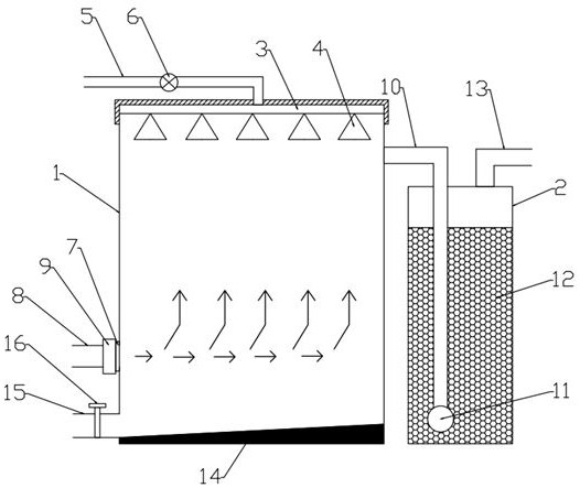
[0015] In conjunction with the accompanying drawings, an energy-saving sludge deodorization device includes a pre-washing tank 1 and a biological filter tank 2. The top of the pre-washing tank 1 is provided with a spray pipe 3, and several spray heads 4 are arranged on the spray pipe 3. , the nozzle 3 adopts a spiral coil, fixed on the top inner wall of the pre-wash tank 1, the spray head 4 is evenly distributed on the coil, the nozzle 3 is connected with the external water pipe 5, and the water ...


PUM


Abstract

The invention discloses an energy-saving sludge deodorization device. The device comprises a pre-washing tank and a biological filtering tank, a spray pipe is arranged at the top in the pre-washing tank, a plurality of spray heads are arranged on the spray pipe, the spray pipe and an external water pipe are connected, a solenoid valve is arranged on the water pipe, an air inlet is formed in a sidewall of the pre-washing tank, an air outlet is formed in the other side wall of the pre-washing tank, air outlet pipe is arranged outside the air outlet, wherein the air outlet pipe is inserted intothe biological filtering tank, deodorizing filler is arranged in the biological filter tank, the air outlet pipe extends to the bottom of the deodorizing filler, an exhaust pipe is arranged at the topof the biological filtering tank, an inclined plate is arranged in the pre-washing tank, a drain pipe is arranged at the bottom end of the inclined plate corresponding to the side wall of the pre-washing tank, and a drain valve is arranged on the drain pipe. The deodorization efficiency is high, up-to-standard emission of foul pollutants is ensured, emission of odorous pollutants is reduced to the maximum extent, and adverse effects of foul smell on ambient air are avoided; the odor treatment amount is large; the deodorization device is small in occupied area, space-saving, economical and practical.

Description

technical field [0001] The invention relates to the technical field of environmental protection equipment, in particular to an energy-saving sludge deodorization device. Background technique [0002] With the continuous acceleration of the urbanization process, the generation and discharge of construction sludge and domestic sludge in the city are also increasing rapidly. While enjoying urban civilization, people are also suffering from the troubles caused by urban garbage. Among them, rivers Sludge, sewage treatment plant press sludge, municipal pipe network dredging sludge, mine sludge, coal gangue, fly ash, construction sludge, boiler cinder and other industrial waste account for a large part, most of which are Some of them are transported to landfills or construction mud dumps. This method not only takes up a lot of land, but also easily causes secondary pollution. After drying and deodorizing river sludge, sewage treatment plant press sludge, and municipal pipe network...

Claims


Application Information

Patent Timeline
Patent Type & Authority Applications(China)
IPC IPC(8): B01D53/84B01D47/06
CPCB01D47/063B01D53/84B01D2251/95Y02A50/20
Inventor 严兰明郑依平
Owner 蕉岭大容环保有限责任公司
Why Eureka
Try Eureka