
Surface treatment method of a curved glass plate

A technology for surface treatment and glass plate, applied in the surface treatment of curved glass plate and the field of surface cleaning of automobile glass, can solve the problems such as the inability to meet the requirements of coating sol-gel coating on the curved glass plate, and achieve the improvement of processing speed, The effect of improving the wetting performance

Active Publication Date: 2022-03-25
FUYAO GLASS IND GROUP CO LTD
View PDF10 Cites 0 Cited by
  • Summary
  • Abstract
  • Description
  • Claims
  • Application Information

AI Technical Summary

Problems solved by technology

[0005] The technical problem to be solved by the present invention is to provide a surface treatment method for curved glass plates in view of the shortcomings that the surface cleaning treatment technology in the prior art cannot meet the requirements of sol-gel coating on curved glass plates.

Method used


Image

  • Surface treatment method of a curved glass plate
  • Surface treatment method of a curved glass plate
  • Surface treatment method of a curved glass plate

Examples


Embodiment 1-8

[0052] The plasma generator spray guns with the power of annular plasma flow of 1000W, 850W, 750W and 650W were used to plasma treat the concave surface of the curved glass plate, and the surface water droplets on the concave surface after plasma treatment were measured at different distances and moving speeds. contact angles and are recorded in Table 1. The distance in Table 1 refers to the distance between the torch of the plasma generator and the concave surface of the curved glass sheet.

[0053] Table 1: Plasma Treatment Results for Examples 1-8

[0054] Power (W) Distance(mm) Movement speed (mm / s) Surface droplet contact angle Example 1 1000 15 40 <5° Example 2 1000 15 80 <10° Example 3 850 10 40 <5° Example 4 850 10 80 <10° Example 5 750 10 40 <5° Example 6 750 10 80 <10° Example 7 650 8 40 <5° Example 8 650 8 80 <10°

[0055] It can be seen from Table 1 that under the action ...

Embodiment 9-10 and comparative example 1

[0057] The plasma generator spray gun with a power of 800W of annular plasma flow was selected, and the concave surface of the curved glass plate was 10mm away from the concave surface of the curved glass plate for plasma treatment. The polished concave surface was coated with a coating, and the curved glass plate with the coating was subjected to a boiling resistance test, and the test results were recorded in Table 2.

[0058] In Table 2,

[0059] Polishing treatment: 15% mass fraction of cerium oxide aqueous dispersion, polished with a plane polishing machine;

[0060] Plasma treatment 30mm / s: the power of the annular plasma flow is 800W, the distance between the spray gun of the plasma generator device is 10mm from the concave surface of the curved glass plate, the moving speed of the annular plasma flow is 30mm / s, and the plasma treatment is performed;

[0061] Plasma treatment 10mm / s: the power of the annular plasma flow is 800W, the distance between the spray gun of th...


PUM

PropertyMeasurementUnit
surface tensionaaaaaaaaaa
diameteraaaaaaaaaa

Abstract

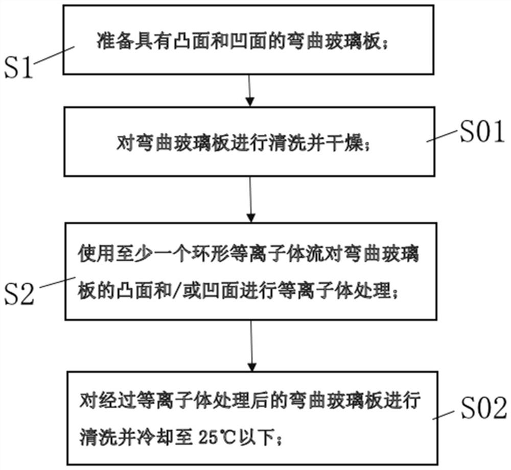
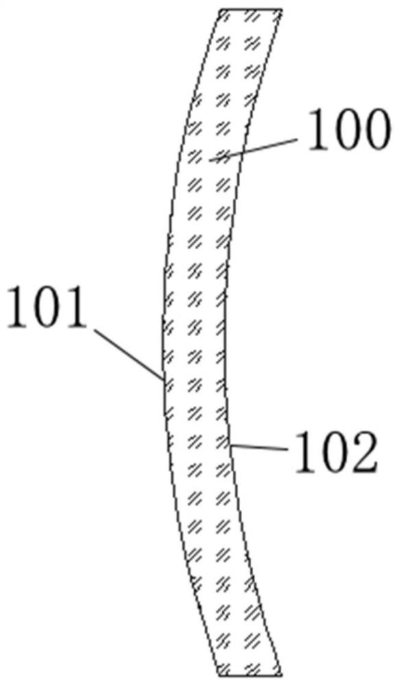
The present invention relates to the technical field of glass surface treatment, in particular to a method for cleaning the surface of automotive glass, and specifically provides a method for surface treatment of a curved glass plate suitable for coating a sol-gel coating, which includes the following steps: S1, preparing a convex surface and a curved glass plate with a concave surface; S2, using at least one annular plasma flow to perform plasma treatment on the convex and / or concave surface of the curved glass plate, and the surface water droplet contact angle of the convex or concave surface after the plasma treatment is less than 10°. The invention can remove oil stains or organic pollutants attached to the glass surface, improve the wettability of the glass surface, and quickly treat the surface tension of the curved glass plate to more than 70mN / m (mN / m), thereby satisfying the subsequent functional coating Layer coating requirements; and can improve the processing speed while meeting the plasma treatment effect, and can adapt to curved glass plates of different shapes, sizes, and profiles.

Description

Technical field: [0001] The invention relates to the technical field of glass surface treatment, in particular to a surface cleaning method for automobile glass, and specifically provides a surface treatment method for a curved glass plate suitable for coating a sol-gel coating. Background technique: [0002] In order to make the automotive glass have the functions of blocking infrared rays, blocking ultraviolet rays, hydrophobicity, anti-fogging or anti-reflection, a sol-gel coating with specific functions can be formed on the surface of the glass plate by the sol-gel method, such as infrared blocking coating. , UV blocking coating, hydrophobic coating, anti-fog coating or anti-reflection coating. [0003] Before applying the sol-gel coating on the surface of the glass plate, it is necessary to thoroughly clean the surface of the glass plate, and even achieve the effect of wetting the surface of the glass plate, so that the surface tension of the glass plate can meet the re...

Claims


Application Information

Patent Timeline
Patent Type & Authority Patents(China)
IPC IPC(8): B08B11/04B08B7/00C03C23/00
CPCB08B11/04B08B7/00C03C23/006
Inventor 阳欢郭善济贾迎辉柯城
Owner FUYAO GLASS IND GROUP CO LTD
Learn More