Uniform flow plating device for inner wall of pipe fitting

A technology of uniform flow and pipe fittings, applied in the direction of current conduction devices, current insulation devices, sealing devices, etc., can solve problems such as uneven coating thickness

Pending Publication Date: 2020-10-30
CHONGQING JIANSHE IND GRP
View PDF0 Cites 2 Cited by
  • Summary
  • Abstract
  • Description
  • Claims
  • Application Information

AI Technical Summary

Problems solved by technology

[0006] The present invention intends to provide a uniform flow plating device on the i...

Method used


Image

  • Uniform flow plating device for inner wall of pipe fitting
  • Uniform flow plating device for inner wall of pipe fitting
  • Uniform flow plating device for inner wall of pipe fitting

Examples


Embodiment 1

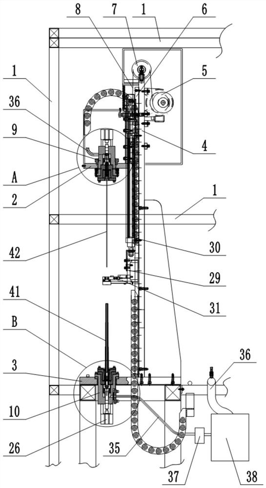
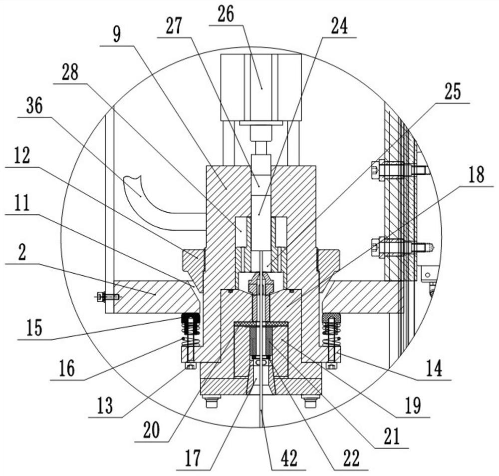
[0037] This embodiment is basically as figure 1 Shown: a uniform flow plating device for the inner wall of the pipe fitting, including a frame 1, a fixing mechanism, a pipe fitting clamping mechanism and an electroplating solution circulation mechanism for filling the electroplating solution into the pipe fitting 41. The fixing mechanism includes an upper mold 2 and a lower mold 3 directly opposite to the upper mold 2, and the lower mold 3 is fixedly installed on the frame 1 by screws. The upper mold 2 is connected with a drive mechanism 1 for driving the upper mold 2 to move. In this embodiment, the drive mechanism 1 includes a guide plate 4 and a drive motor 5 fixedly connected to the guide plate 4. The upper mold 2 is vertically slidably connected to the guide plate. On the plate 4, specifically, the guide plate 4 is welded with a vertically arranged guide rail 6, and the right end of the upper mold 2 is fixedly mounted on the slide block of the guide rail 6 by screws. The...

Embodiment 2

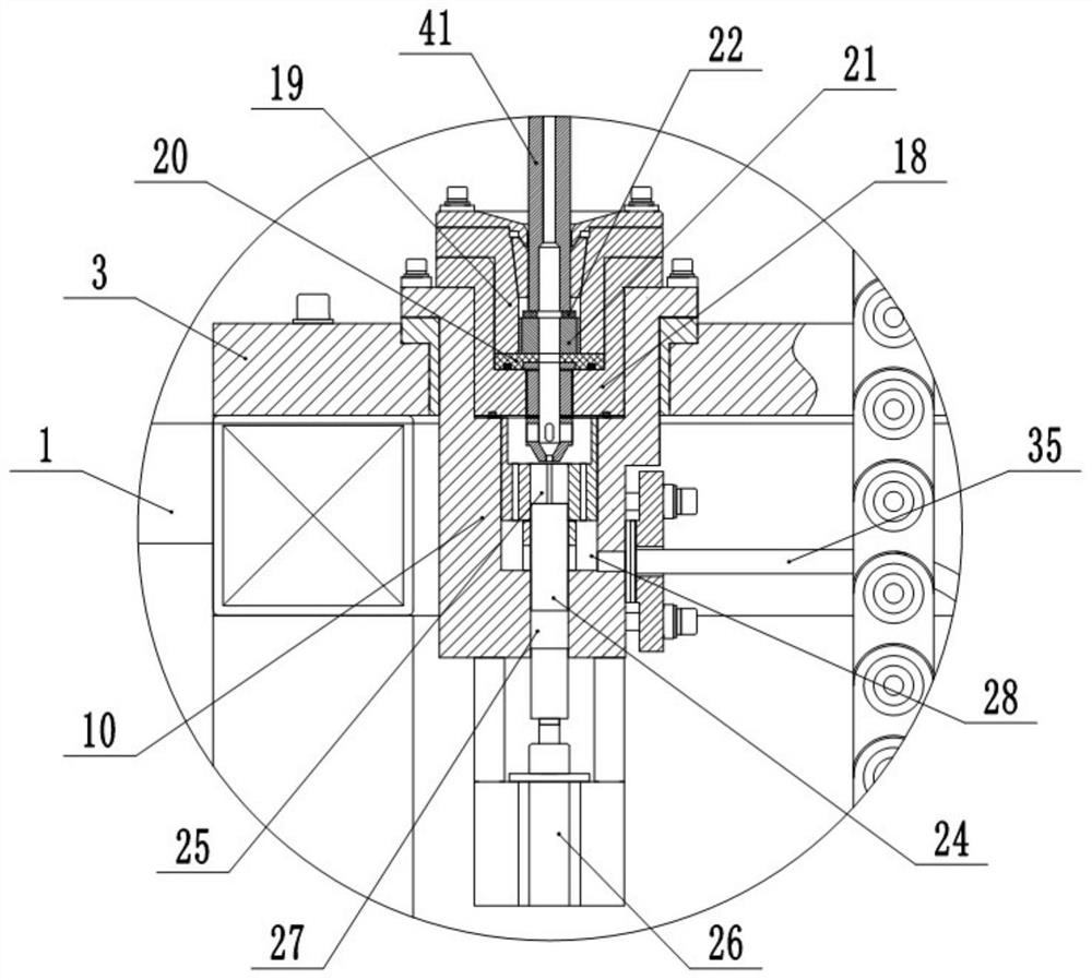
[0057] The difference between this embodiment and Embodiment 1 is that: Figure 5 As shown, the bottom of the lower mold 3 is fixed with a leaking liquid contact box 39 by screws, and the bottom wall of the leakage liquid contact box 39 is provided with a round hole for the output end of the telescopic cylinder 26 to pass through. The bottom wall of 39 is bonded with seal ring three 40, and the output end of telescopic cylinder 26 passes seal ring three 40.

[0058] In this embodiment, the telescopic cylinder 26 on the lower fixed block 10 drives the conductive rod 24 to move downward or upward. Therefore, during the movement of the conductive rod 24, the seal 27 also moves relative to the guide hole. At this time, the electroplating solution may flow from the guide hole. The hole oozes out and drips in the leaking liquid contact box 39 to prevent the electroplating solution from directly dripping on the telescopic cylinder 26 and the ground.


PUM


Abstract

The invention relates to the field of plating, and discloses an uniform flow plating device for an inner wall of a pipe fitting. The device comprises a fixing mechanism, a pipe clamping mechanism andan electroplating solution circulation mechanism for filling pipe fittings with electroplating solution. The fixing mechanism comprises an upper mold and a lower mold. Both the upper mold and the lower mold are connected with fixing blocks. The fixing blocks are provided with fixing holes for fixing the end of the pipe fittings, and the fixing blocks are further provided with guide holes communicating with the fixing holes. The guide holes are provided with tension units for fixing the end of an anode. Both ends of the anode are electrically connected with a power supply part. The fixing blocks are provided with an electroplating solution flow channel connected with the guide holes. The pipe clamping mechanism comprises a guide hole intermittently leading to the anode and a conductive connecting piece intermittently electrically connected with the pipe. By forcibly energizing both ends of the anode, the device can realize uniform flow plating on the inner wall of the pipe fitting, thereby improving the uniformity of the coating thickness of the inner wall of the pipe fitting, improving the product qualification rate, and reducing the production cost.

Description

technical field [0001] The invention relates to the field of electroplating equipment, in particular to a uniform flow plating device for the inner wall of a pipe fitting. Background technique [0002] The electroplating process is a process of plating a layer of metal or alloy on the surface of some metals (ie workpieces) by using the principle of electrolysis. The coating formed by the electroplating process changes the properties of the surface of the workpiece or the size of the workpiece, thereby improving the oxidation resistance of the workpiece. (such as rust), wear resistance, reflective properties, and increase the aesthetics of the workpiece. In addition, the use of electroplating technology can also repair the workpiece with surface wear. [0003] During electroplating, the plating metal or other insoluble material is the anode, and the workpiece to be plated is the cathode. The electroplating process is carried out in the electroplating solution containing the p...

Claims


Application Information

Patent Timeline
IPC IPC(8): C25D7/04C25D5/08C25D5/02C25D17/06C25D17/10C25D17/00
CPCC25D5/026C25D5/08C25D7/04C25D17/004C25D17/007C25D17/008C25D17/06C25D17/10
Inventor 杨平
Owner CHONGQING JIANSHE IND GRP
Why Eureka
Try Eureka