Modular engine hydraulic braking device

A hydraulic brake and engine technology, applied in engine components, machines/engines, valve devices, etc., can solve the problems of difficult processing, complex assembly procedures, and high processing accuracy requirements

Pending Publication Date: 2020-10-30
ZHEJIANG LIMING INTELLIGENT MFG CO LTD
View PDF2 Cites 4 Cited by
  • Summary
  • Abstract
  • Description
  • Claims
  • Application Information

AI Technical Summary

Problems solved by technology

[0004] However, the control mechanism and executive mechanism of the above-mentioned engine brake device need to be assembled on ...

Method used


Image

  • Modular engine hydraulic braking device
  • Modular engine hydraulic braking device
  • Modular engine hydraulic braking device

Examples


Embodiment Construction

[0046] The embodiments of the present invention will be further described below in conjunction with the drawings:

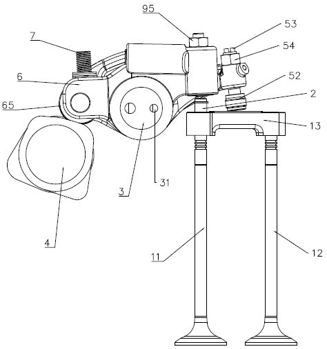
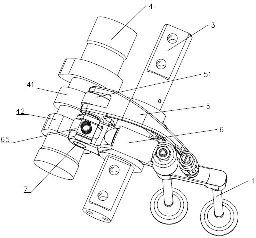
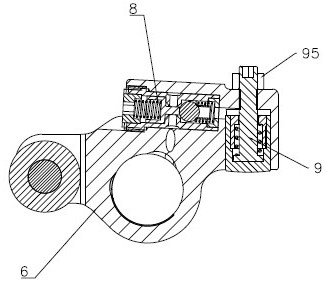
[0047] As shown in the figure, a modular engine hydraulic brake device includes exhaust valve 1, sliding pin 2, rocker shaft 3, cam shaft 4, exhaust rocker arm 5, auxiliary rocker arm 6, elastic element 7, Control mechanism 8, executive mechanism 9.

[0048] The exhaust valve 1 includes a first exhaust valve 11, a second exhaust valve 12, and a valve bridge 13 transversely disposed on the first exhaust valve 11 and the second exhaust valve 12. The first exhaust valve 11 and The second exhaust valve 12 adopts a mushroom valve for controlling the flow of gas between the combustion chamber and the intake and exhaust manifolds in the engine.

[0049] The sliding pin 2 is arranged in the valve bridge 13, one end of which is in contact with the first exhaust valve 11, and the other end passes through the valve bridge 13. When the sliding pin 2 receives a large enough force, ...


PUM


Abstract

The invention relates to a modular engine hydraulic braking device. The modular engine hydraulic braking device is characterized in that a control mechanism includes a shell, a one-way valve group anda control valve group, the one-way valve group and the control valve group are installed in the shell, and the control mechanism is installed in a control cavity of an auxiliary rocker arm; an actuator includes an adjusting bolt, an executive plunger, a third spring seat and a third spring, and the actuator is installed in an executive cavity of the auxiliary rocker arm. The modular engine hydraulic braking device has the advantages that the control mechanism and the actuator form independent modular design, easy processing and simple assembly process are achieved, the processing efficiency can be greatly improved, and the production cost is reduced.

Description

Technical field [0001] The invention relates to a medium and heavy-duty diesel and natural gas engine, in particular to a modular hydraulic brake device for the engine. Background technique [0002] Engine braking technology means that the driver lifts the accelerator pedal, releases the clutch, and uses the compression resistance generated during the compression stroke of the engine, as well as the braking force formed by the intake and exhaust resistance and friction on the driving wheels. Make it brake the car. Engine braking technology is divided into compression engine braking, deflated engine braking and partially deflated engine braking. Compression engine brake is to open the exhaust valve or auxiliary valve near compression top dead center; deflated engine brake is to open the exhaust valve throughout the engine cycle; partially deflated engine brake is to open most of the stroke of the engine cycle Exhaust valve. The application of engine braking technology effective...

Claims


Application Information

Patent Timeline
IPC IPC(8): F01L13/06
CPCF01L13/06
Inventor 俞黎明俞振寰
Owner ZHEJIANG LIMING INTELLIGENT MFG CO LTD
Why Eureka
Try Eureka