Oil injection method

A technology of fuel injection volume and single injection, applied in fuel injection control, engine control, machine/engine, etc., can solve the problems of difficult engine cold start, unfavorable oil film evaporation on the cylinder liner, and inability to control temperature, so as to improve engine oil Effects of Dilution and Oil Rise Problems

Active Publication Date: 2020-10-30
CHONGQING CHANGAN AUTOMOBILE CO LTD
View PDF9 Cites 7 Cited by
  • Summary
  • Abstract
  • Description
  • Claims
  • Application Information

AI Technical Summary

Problems solved by technology

However, when the ambient temperature is extremely low (-30°C), the engine thermal management system cannot control the wall temperature of the combustion chamber within the range conducive to fuel evaporation, resulting in the formation of the oil film on the cylinder liner cannot be evaporated quickly, and the oil level Ascent issues are hard to get under control
[0004] Most of the existing technologies control the fuel injection process in the intake and compression strokes of the engine. This type of fuel injection strategy has a greater risk of oil level rise in extremely cold conditions, mainly because: First, under extremely cold conditions (-30°C ), the temperature of the fuel tank is basically the same as the ambient temperature, and the fuel supply system has little effect on heating the fuel, resulting in the temperature of the oil jet entering the combustion chamber close to the ambient temperature. The increased penetration distance increases the risk of the oil beam hitting the cylinder wall to form an oil film; secondly, it is difficult to start the engine cold under extremely cold conditions, and the ECU (Electronic Control Unit) adopts a strategy of enriching the mixture to achieve a rapid engine start and increase the fuel injection volume Further aggravates the formation of cylinder liner oil film; moreover, when the engine is in extremely cold working conditions, the cooling system heats up slowly, and the engine water temperature is kept in a low range, resulting in low wall temperature, which is not conducive to the evaporation of oil film on the cylinder liner
Therefore, based on the existing technology, it is impossible to effectively control the rise of the oil level of the engine in the extremely cold environment.

Method used


Image

  • Oil injection method
  • Oil injection method

Examples


Embodiment Construction

[0018] The present invention will be further described below in conjunction with accompanying drawing.

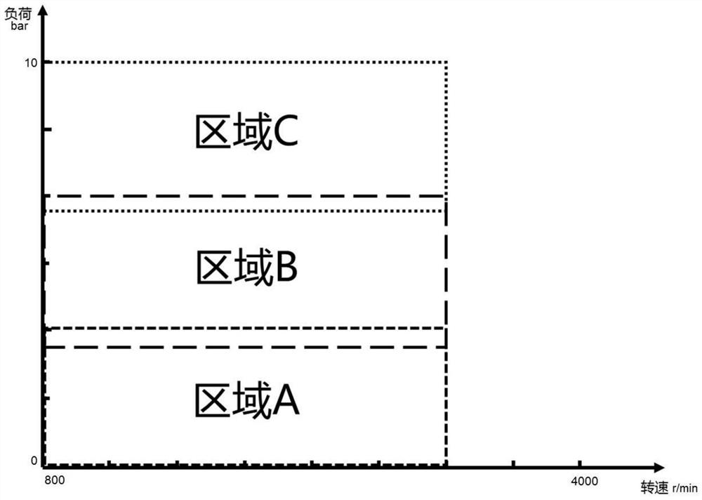
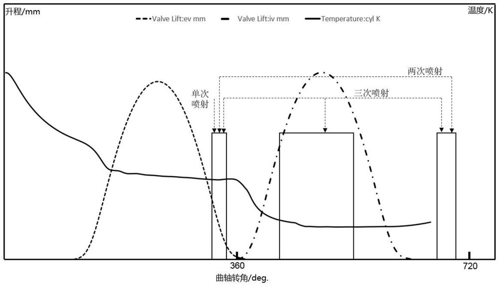
[0019] Such as figure 1 and figure 2 As shown, the present invention proposes a fuel injection method for alleviating the problem of rising oil level of supercharged direct injection engine under extremely cold conditions, specifically as follows:

[0020] Such as figure 1 As shown, when the working condition of the engine is in region A, the engine is running in the low-load region, the temperature of the fuel tank under extremely cold conditions (-30°C) is basically the same as the ambient temperature, and the fuel supply system has little effect on heating the fuel , causing the temperature of the oil beam entering the combustion chamber to be close to the ambient temperature, and when the engine is in this area, the fuel temperature is lower, so when the engine works in the range of area A, a single injection is performed in each working cycle, and at the exhaust top...


PUM


Abstract

The invention relates to an oil injection method. According to the method, when an engine is at a low load, injection is performed once in each work cycle, and oil injection is completed before exhaust stop; when the engine is at an intermediate load, injection is performed twice in each work cycle, and the first oil injection is completed before exhaust stop; and when the engine is at a high load, injection is performed three times in each work cycle, and the first oil injection is completed before exhaust stop. According to the advantage that the temperature in a cylinder in an exhaust stroke of the engine is higher than that in an intake stroke of the engine, a part of the oil injection process is controlled in a later period of the exhaust stroke; on one hand, the temperature of residual gas in the cylinder is utilized to the maximum to accelerate fuel evaporation, the spray penetration distance is shortened, and therefore wall wetting of a cylinder jacket is lowered; and on the other hand, evaporation of an oil film on the wall of the cylinder is accelerated according to the favorable condition that the temperature of the cylinder jacket is high in the later period of the exhaust stroke. Therefore, the method can substantially relieve the problems of oil dilution and oil level rise of a direct injection engine in an extremely cold environment.

Description

technical field [0001] The invention relates to an automobile engine, in particular to a fuel injection method. Background technique [0002] In-cylinder direct injection (GDI) is an important means to improve the fuel economy and power of gasoline engines. However, in direct injection engines, liquid fuel directly collides with the cylinder liner, forming a liquid oil film on the cylinder liner. This part of the liquid oil film is During the process, the piston ring will be scraped into the oil pan, causing the oil level to rise, the kinematic viscosity of the oil to decrease, the performance of the oil to be damaged, and the establishment of the lubricating oil film of the high-speed moving parts of the engine to be affected, resulting in a decrease in the overall reliability of the engine. The main reasons for the rise of the oil level of the direct injection engine in the cylinder are: the shape of the combustion chamber is unreasonable, the fuel injection control method...

Claims


Application Information

Patent Timeline
Patent Type & Authority Applications(China)
IPC IPC(8): F02D41/40F02D41/04
CPCF02D41/405F02D41/047
Inventor 向璐沈惠贤蒲运平郑建军曾庆强
Owner CHONGQING CHANGAN AUTOMOBILE CO LTD
Why Eureka
Try Eureka