
Optical detector based on thermoelectric material

A pyroelectric material and photodetector technology, applied in the field of photodetection, can solve the problems of low light absorption efficiency and low photodetector performance

Inactive Publication Date: 2020-10-30
中山科立特光电科技有限公司
View PDF0 Cites 0 Cited by
  • Summary
  • Abstract
  • Description
  • Claims
  • Application Information

AI Technical Summary

Problems solved by technology

At present, the light absorption efficiency of photodetectors is low, making the performance of photodetectors not high

Method used


Image

  • Optical detector based on thermoelectric material
  • Optical detector based on thermoelectric material

Examples


Embodiment 1

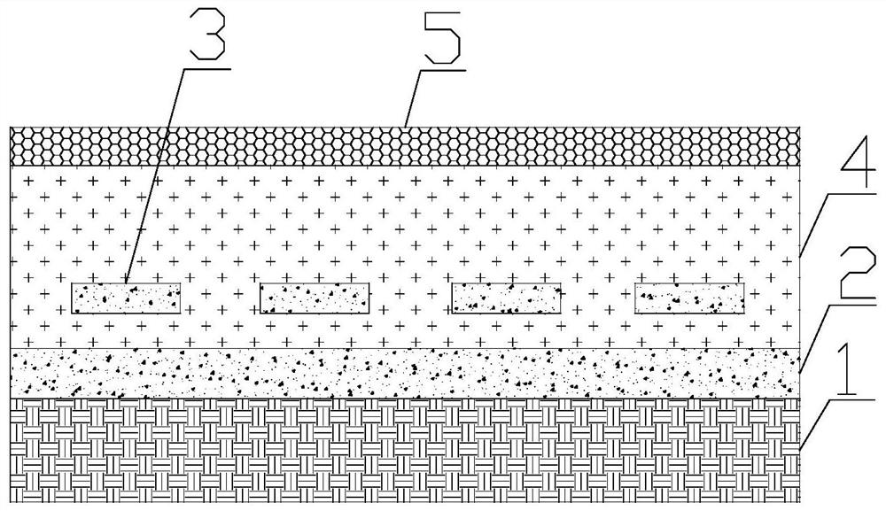
[0020] The invention provides a photodetector based on pyroelectric material. Such as figure 1 As shown, the photodetector includes a substrate 1 , a first thin film layer 2 , a micro-nano structure array layer 3 , a pyroelectric material part 4 , and a conductive thin film layer 5 . The first film layer 2 is placed on the substrate 1, and the substrate 1 is an insulating material. Preferably, the substrate 1 is made of silicon dioxide material. The thermoelectric material part 4 is placed on the first film layer 2, and the material of the thermoelectric material part 4 is lead zirconate titanate, lithium tantalate, lithium niobate, gallium nitride, and cesium nitrate. The micro-nano structure array layer 3 is disposed in the thermoelectric material part 4 . The micro-nano structure array layer 3 is not in contact with the first film layer 2, the micro-nano structure array layer 3 is parallel to the first film layer 2, and the micro-nano structure array layer 3 includes per...

Embodiment 2

[0027] On the basis of Example 1, the micro-nano structure is L-shaped, the two arms of the L-shape are parallel to the first film layer 2, and the lengths of the two arms of the L-shape are unequal. In this way, the micro-nano structure is a planar chiral structure, and the composite structure formed by the micro-nano structure and the first thin film layer 2 has different absorptions for left-handed circularly polarized light and right-handed circularly polarized light, so that the detector in the present invention The detection of the polarization state of the incident light can be realized. In addition, the thickness of the two arms of the L is different to increase the chirality of the L-shaped structure, making it more different in the absorption of left-handed circularly polarized light and right-handed circularly polarized light, thereby achieving a higher sensitivity to the polarization state of incident circularly polarized light detection.

Embodiment 3

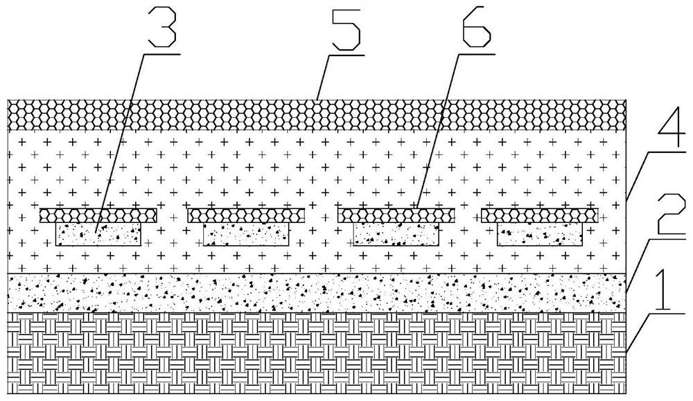
[0029] On the basis of Example 2, such as figure 2 As shown, the graphene block 6 is arranged on the micro-nano structure. Due to the confinement effect of the graphene block 6 on the electromagnetic wave, the light between the micro-nano structure and the first thin film layer 2 is more concentrated, and the absorption difference between the left-handed circularly polarized light and the right-handed circularly polarized light in this region is greater, so that it can realize Higher sensitivity detection of polarization state of incident circularly polarized light.


PUM


Abstract

The invention provides an optical detector based on a thermoelectric material. A first film layer is arranged on a substrate; a thermoelectric material part is arranged on the first thin film layer, amicro-nano structure array layer is arranged in the thermoelectric material part, the micro-nano structure array layer is not in contact with the first thin film layer, the micro-nano structure arraylayer is parallel to the first thin film layer, the micro-nano structure array layer comprises micro-nano structures arranged regularly in a single layer, and the conductive thin film layer is arranged on the top surface of the thermoelectric material part. During application, the conductive film layer and the first template layer are connected with an electrode, and light to be detected irradiates from one side of the conductive film layer. Light penetrates through the conductive thin film layer and the thermoelectric material part, is absorbed by the first thin film layer and the micro-nanostructure array layer and generates heat, and temperature difference in the thermoelectric material part causes lattice structure polarization, so that the thermoelectric material part generates an electric field, and light detection is realized by detecting the electric field. Because the micro-nano structure array layer and the first film layer have stronger light absorption capability, the optical detector has the advantage of high light detection sensitivity.

Description

technical field [0001] The invention relates to the field of photodetection, in particular to a photodetector based on pyroelectric materials. Background technique [0002] With the advancement of science and technology, the application range of photodetectors is becoming wider and wider, and the requirements for the sensitivity and wavelength resolution of photodetectors are getting higher and higher. Currently, the light absorption efficiency of photodetectors is low, making the performance of photodetectors not high. Contents of the invention [0003] In order to solve the above problems, the present invention provides a photodetector based on pyroelectric materials, which includes a substrate, a first thin film layer, a micro-nano structure array layer, a thermoelectric material part, and a conductive thin film layer; the first thin film layer Placed on the substrate, the thermoelectric material part is placed on the first film layer, the micro-nano structure array la...

Claims


Application Information

Patent Timeline
Patent Type & Authority Applications(China)
IPC IPC(8): G01J1/42H01L35/22H10N10/855
CPCG01J1/42H10N10/855
Inventor 不公告发明人
Owner 中山科立特光电科技有限公司
Learn More