
Liquid cooling plate structure size optimization method based on Hyperstudy and Fluent joint simulation

An optimization method and a technology of structural size, applied in design optimization/simulation, special data processing applications, geometric CAD, etc., can solve problems such as thermal runaway, long time consumption of liquid cooling plates, and impact on service life, etc., to meet the requirements of reducing modeling , shorten the optimization cycle, and reduce labor costs

Pending Publication Date: 2020-10-30
HUAIAN JUNSHENG NEW ENERGY TECHNOLOGY CO LTD
View PDF0 Cites 3 Cited by
  • Summary
  • Abstract
  • Description
  • Claims
  • Application Information

AI Technical Summary

Problems solved by technology

[0004] In the existing liquid cooling plate, the width of each flow channel is usually equal, but due to the different length and shape of each flow channel, the flow distribution in each flow channel is uneven, which easily leads to the gap between the regions in the power battery system. The heat dissipation effect is uneven, which leads to poor temperature consistency in the overall power battery system, affects the service life, and even causes the risk of thermal runaway;
[0005] In addition, each channel of the liquid cold plate is usually optimized manually, and the optimal solution is often not obtained after repeated operations, which makes the optimization of the liquid cold plate time-consuming and inefficient.

Method used


Image

  • Liquid cooling plate structure size optimization method based on Hyperstudy and Fluent joint simulation
  • Liquid cooling plate structure size optimization method based on Hyperstudy and Fluent joint simulation
  • Liquid cooling plate structure size optimization method based on Hyperstudy and Fluent joint simulation

Examples


Embodiment Construction

[0027] The following will clearly and completely describe the technical solutions in the embodiments of the present invention with reference to the accompanying drawings in the embodiments of the present invention. Obviously, the described embodiments are only some, not all, embodiments of the present invention. Based on the embodiments of the present invention, all other embodiments obtained by persons of ordinary skill in the art without making creative efforts belong to the protection scope of the present invention.

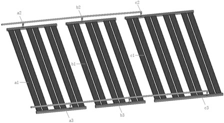
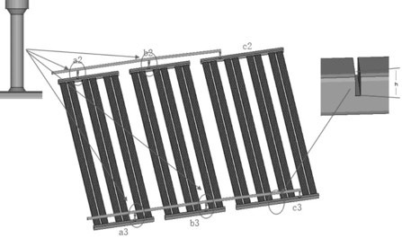
[0028] According to the existing technology, establish as figure 1 The liquid cold plate model shown, in this model, includes three groups of liquid cold plates a / b / c, wherein the first group of liquid cold plates a includes the liquid cold plate main board a1, branch pipe a2 and spoiler a3; The second group of liquid-cooled plates b includes the main board of the liquid-cooled plate b1, the branch pipe b2 and the spoiler b3; the third group of liquid-cooled p...


PUM


Abstract

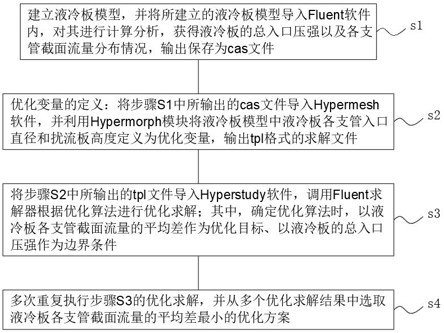
The invention belongs to the technical field of liquid cooling plate structure optimization, and discloses a liquid cooling plate structure size optimization method based on Hyperstudy and Fluent joint simulation. The method comprises the following steps: S1, importing a liquid cooling plate model into Fluent software, calculating and analyzing the liquid cooling plate model to obtain the total inlet pressure of a liquid cooling plate and the flow distribution condition of the section of each branch pipe, and outputting and storing the total inlet pressure and the flow distribution condition as cas files; s2, importing the cas file output in the step S1 into Hypermesh software, defining the inlet diameter of each branch pipe of a liquid cooling plate and the height of a spoiler in a liquidcooling plate model as optimization variables by utilizing a Hypermorph module, and outputting a solution file in a tpl format; s3, importing the tpl file output in the step S2 into Hyperstudy software, and calling a Fluent solver to carry out optimization solution according to an optimization algorithm. In conclusion, a software simulation optimization mode is used for replacing manual optimization, the optimization period is effectively shortened, the optimization efficiency is improved, and the labor cost is reduced; moreover, software simulation is combined simulation carried out by utilizing Hyperstudy and Fluent, so that the modeling requirement during optimization can be reduced.

Description

technical field [0001] The invention belongs to the technical field of liquid-cooled plate structure optimization, and in particular relates to a liquid-cooled plate structure size optimization method based on Hyperstudy and Fluent joint simulation. Background technique [0002] Liquid cold plates are often used in the cooling system of automotive power batteries. [0003] In the power battery system, the battery generates excess heat. The heat is transferred through the contact between the battery or the module and the surface of the liquid cooling plate, and is finally taken away by the cooling liquid passing through the internal flow channel of the liquid cooling plate to realize the heat dissipation of the power battery. [0004] In the existing liquid cooling plate, the width of each flow channel is usually equal, but due to the different length and shape of each flow channel, the flow distribution in each flow channel is uneven, which easily leads to the gap between th...

Claims


Application Information

Patent Timeline
IPC IPC(8): G06F30/17G06F30/20
CPCG06F30/17G06F30/20
Inventor 夏明博
Owner HUAIAN JUNSHENG NEW ENERGY TECHNOLOGY CO LTD
Learn More