
Traction inverter control system and PWM modulation method

A traction inverter and control system technology, which is applied in the direction of converting AC power input to DC power output, output power conversion devices, electrical components, etc. complex issues

Active Publication Date: 2020-10-30
CRRC QINGDAO SIFANG ROLLING STOCK RES INST
View PDF14 Cites 0 Cited by
  • Summary
  • Abstract
  • Description
  • Claims
  • Application Information

AI Technical Summary

Problems solved by technology

However, the SVPWM modulation method of the traditional three-level inverter is more complicated in the realization of the control method, including the judgment of the reference vector sector and the calculation of the basic vector action time, etc., which involve more trigonometric function operations and table queries. , the modulation algorithm is extremely cumbersome, so it will bring a large burden to the controller, which will lead to problems such as poor control accuracy of the controller hardware, unstable modulation mode switching, and poor output waveform quality, which is not conducive to the development of three-level inverters.

Method used


Image

  • Traction inverter control system and PWM modulation method
  • Traction inverter control system and PWM modulation method
  • Traction inverter control system and PWM modulation method

Examples


Embodiment Construction

[0097] Hereinafter, specific embodiments of the present invention will be further described in conjunction with the accompanying drawings.

[0098] In the description of the present invention, it should be noted that the terms "first", "second", "third" and "fourth" are used for description purposes only, and should not be understood as indicating or implying relative importance.

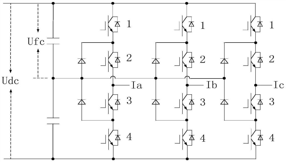
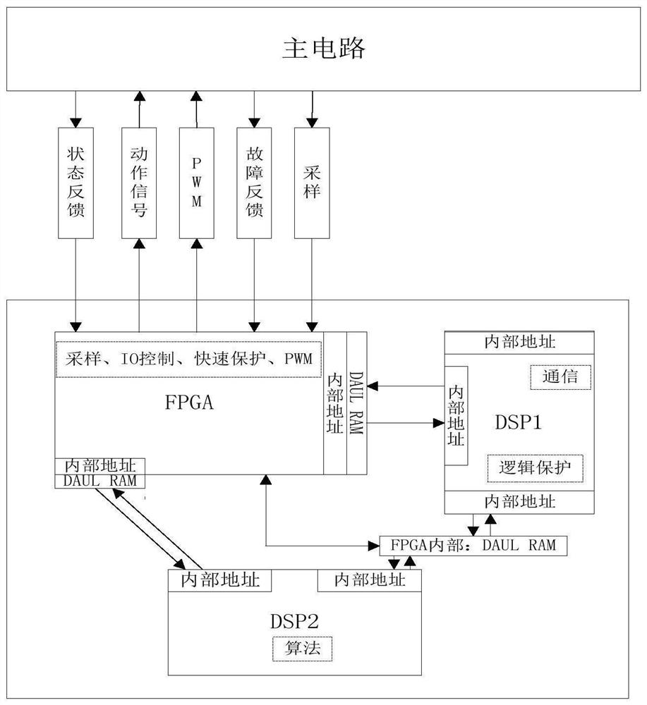
[0099] The present invention firstly provides a traction inverter control system, which is used to realize the operation control of the traction inverter. The control system includes a main circuit, a first processor, a second processor and a third processor; the main circuit includes an inverter unit, the input end of the main circuit is connected to a DC bus, and the output end of the main circuit is connected to a load motor; the main circuit The circuit further includes a clamping diode and two voltage-dividing capacitors with equal capacitances connected to the DC bus, and the midpoint of the t...


PUM


Abstract

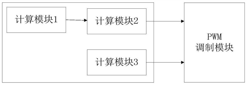
The invention provides a traction inverter control system and a PWM modulation method. The system comprises a main circuit, a first processor, a second processor and a third processor. The main circuit comprises an inversion unit, the input end of the inversion unit is connected with a DC bus, and the output end of the inversion unit is connected with a load motor. The first processor is connectedwith the main circuit; the second processor is connected with the first processor and is used for generating an excitation inductance signal, an excitation current signal and a torque current signalof the load motor; the third processor is connected with the second processor and is used for generating a zero-sequence voltage regulation quantity signal, a load motor control voltage signal and a load motor control frequency signal and carrying out PWM modulation calculation to generate a modulation signal; the first processor receives the modulation signal, modulates the modulation signal to generate a switching pulse signal and sends the switching pulse signal to the inversion unit. The modulation method can realize smooth and stable switching among the modulation modes, inhibits startingcurrent impact, and is easy to realize, reliable and stable based on the control system.

Description

technical field [0001] The invention belongs to the field of traction inverters, in particular to a traction inverter control system and a PWM modulation method. Background technique [0002] The three-level traction inverter has the advantages of low switching frequency, low loss, high efficiency, reduced harmonic content, improved output waveform quality, and reduced withstand voltage requirements for switching devices. It has been widely used in high-speed EMUs. And gradually get attention in the application of subway vehicles. [0003] At present, the three-level inverter control system mostly uses dual processors to work together. DSP is responsible for the real-time operation of complex control algorithms as the main processor, and FPGA is responsible for AD sampling control and PWM signal generation as the co-processor, which reduces the burden on DSP. Budget burden, the control system can run complex grid-connected control programs, which improves the real-time perf...

Claims


Application Information

Patent Timeline
IPC IPC(8): H02M7/483H02M1/088
CPCH02M1/088H02M7/483
Inventor 林显琦杨其林郝遥迪毕京斌
Owner CRRC QINGDAO SIFANG ROLLING STOCK RES INST
Learn More