
Manufacturing method of long pipe fitting with straight flanges at two ends

A manufacturing method and flange technology, applied in manufacturing tools, forming tools, applications, etc., can solve the problems of weak anti-fatigue impact performance, low material utilization rate, increased surface treatment, etc., and achieve excellent anti-fatigue impact performance, improve The effect of material utilization, thickness and length savings

Active Publication Date: 2020-11-03
INST OF MACHINERY MFG TECH CHINA ACAD OF ENG PHYSICS
View PDF5 Cites 2 Cited by
  • Summary
  • Abstract
  • Description
  • Claims
  • Application Information

AI Technical Summary

Problems solved by technology

[0003] For the processing and manufacturing of this type of parts, the current relatively traditional method is to adopt the method of integral machining, welding and integral upsetting, which mainly has the following shortcomings: 1) During the integral machining process, a large amount of material is removed, and the material utilization rate is low. The processing cycle is long; 2) For thin-walled long pipe fittings, the overall machining is more difficult, and the product accuracy is not easy to guarantee; 3) During the overall machining process, the material fiber streamline is cut off, and the fatigue impact resistance is weak; 4) The welding can obtain The appearance of the parts is not beautiful, and there are problems such as long-term use reliability. It is often necessary to increase surface treatment and other work, which is not conducive to environmental protection; 5) The overall upsetting process consumes a lot of energy for heating, and there is a risk of coarse grains in the non-upsetting area , at the same time, in order to avoid the instability of the barrel section during the upsetting process, the wall thickness of the pipe used is relatively thick, and the material utilization rate is not high
In addition, for the overall upsetting of long pipe fittings, the required mold is too long, the equipment is large, and the manufacturing cost is high

Method used


Image

  • Manufacturing method of long pipe fitting with straight flanges at two ends
  • Manufacturing method of long pipe fitting with straight flanges at two ends

Examples


Embodiment 1

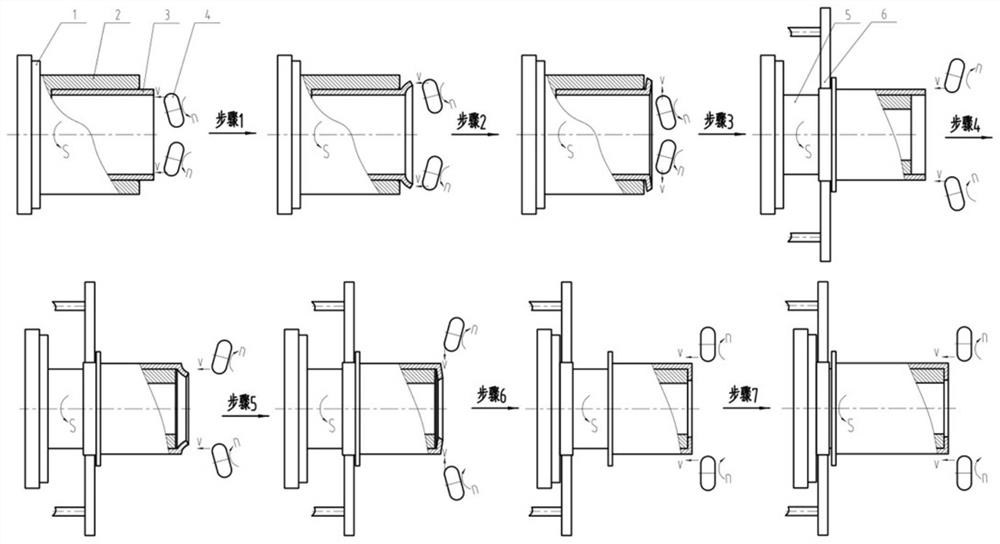
[0033] This embodiment uses Q235 steel as a typical material to elaborate on the method for manufacturing long pipe fittings with straight flanges at both ends of the present invention. The specific process is as follows figure 1 Shown:

[0034] Step 1. Set the Q235 tube blank 3 with an outer diameter of φ320mm, a wall thickness of 20mm, and a length of 500mm in the outer flange forming mold set 2 with an inner diameter of φ321mm connected to the main shaft 1 of the equipment, and confirm that the tube blank protrudes to a length of 50mm. The main shaft 1 rotates at a speed of S=100r / min, and drives the outer flange forming die set 2 and the tube blank 3 to rotate synchronously, and then controls the two rotary wheels 4 with an outer diameter of φ100mm and a rounded corner R40mm symmetrically arranged to move along the inner side of the tube blank 3 The axial direction is linearly fed at the speed of v=80mm / min, and at the same time driven by the rotating speed of n≈320r / min t...


PUM


Abstract

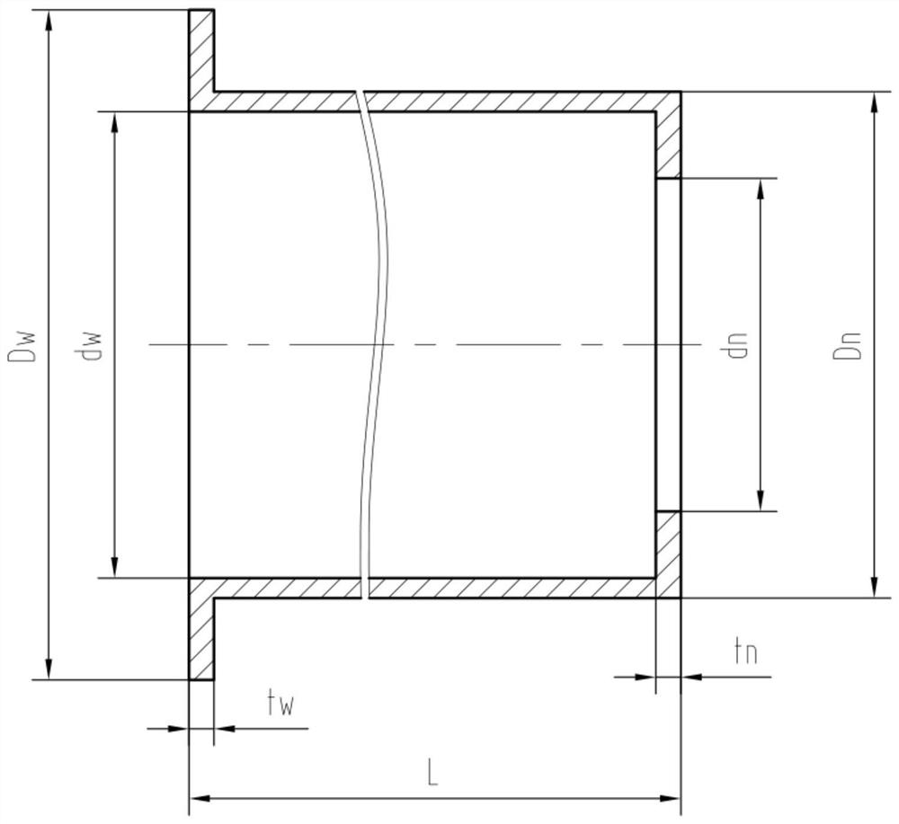
In order to overcome the defects in the prior art, the invention provides a manufacturing method of a long pipe fitting with straight flanges at the two ends. The manufacturing method is high in material utilization rate, high in production efficiency and good in product quality, and comprises the following steps of S1, forming inner circular beads at the outer flange ends of a pipe blank by adopting an internal spinning reverse expanding and local upsetting extruding composite technology; S2, realizing integral preforming of outer flanges by adopting a plane rotary rolling incremental formingtechnology; S3, realizing accurate forming of the outer flanges through a plane outward-pulling and flattening technology; S4, forming outer circular beads at the inner flange end of the pipe blank by adopting an external spinning reverse reducing and local upsetting extruding composite technology; S5, realizing integral preforming of inner flanges through the plane rotary rolling incremental forming technology; S6, adopting a plane inward-drawing and flattening technology to realize accurate forming of the inner flanges; and S7, forming a straight section of the long pipe fitting by adoptinga powerful spinning technology. The whole manufacturing process is easy to operate, and the manufacturing method does not need auxiliary heating, machining and other work, and is high in digitizationdegree, high in product precision, good in consistency, low in labor intensity, environment-friendly, material-saving, high in quality and efficient.

Description

technical field [0001] The invention belongs to the technical field of precise plastic processing, and in particular relates to a method for manufacturing a long pipe fitting with straight flanges at both ends. Background technique [0002] As a typical part, long pipe fittings are widely used in military and civil fields such as aerospace, weapons, nuclear industry and pipelines. Based on the needs of connection and assembly, the ends of long pipe fittings often have flange structures. In recent years, the demand for long pipe fittings with both ends flange structure is increasing day by day, especially the demand for long pipe fittings with straight flanges at both ends is urgent. [0003] For the processing and manufacturing of this type of parts, the current relatively traditional method is to adopt the method of integral machining, welding and integral upsetting, which mainly has the following shortcomings: 1) During the integral machining process, a large amount of ma...

Claims


Application Information

Patent Timeline
Patent Type & Authority Applications(China)
IPC IPC(8): B21D51/02B21D22/14B21D19/04B21D41/04B21D37/10
CPCB21D51/02B21D22/14B21D19/046B21D41/04B21D37/10
Inventor 崔旭昌杨文华郝爱国赵建斌郝花蕾秦林新廖哲
Owner INST OF MACHINERY MFG TECH CHINA ACAD OF ENG PHYSICS
Learn More