A dual-sludge biologically enhanced sewage treatment device

A sewage treatment device and bio-augmentation technology, applied in biological water/sewage treatment, water/sludge/sewage treatment, return water treatment, etc. question

Active Publication Date: 2021-05-14
TONGJI UNIV
View PDF6 Cites 0 Cited by
  • Summary
  • Abstract
  • Description
  • Claims
  • Application Information

AI Technical Summary

Problems solved by technology

[0003] However, the biochemical sewage treatment device in the prior art has the disadvantages of large floor space, long sewage treatment time, and unsatisfactory treatment effect.

Method used


Image

  • A dual-sludge biologically enhanced sewage treatment device
  • A dual-sludge biologically enhanced sewage treatment device

Examples


Embodiment 1

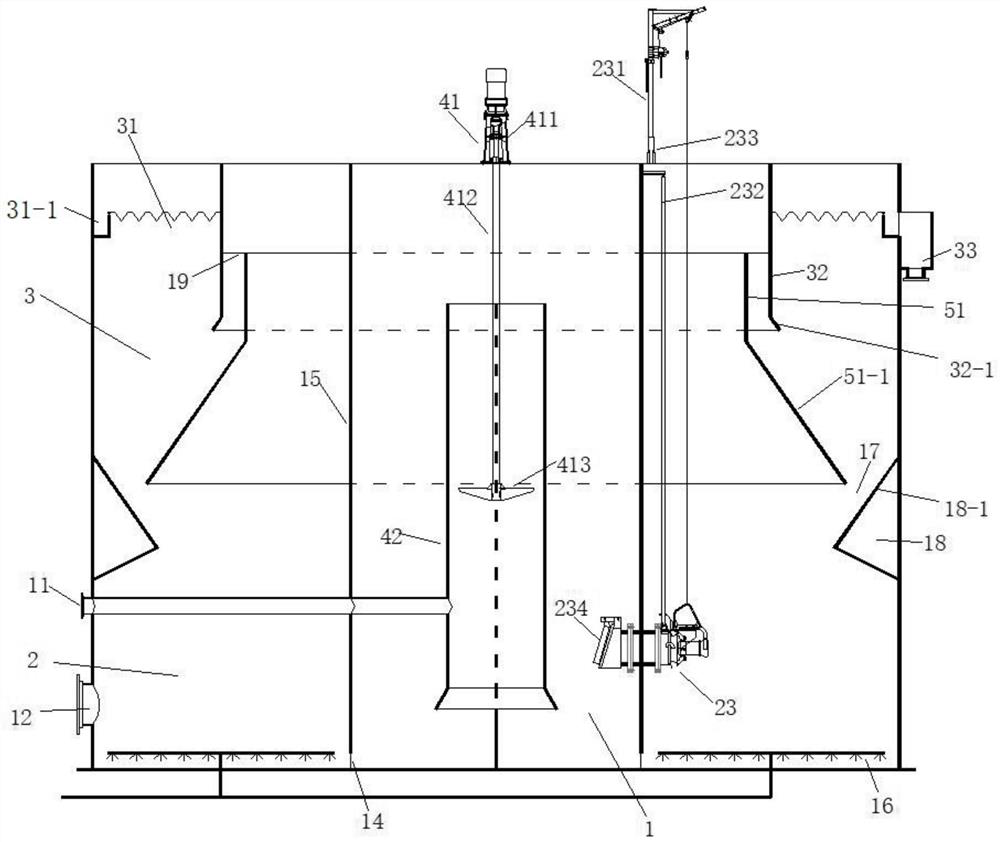
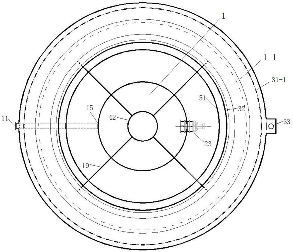
[0033] Such as Figure 1-2 As shown, it is a kind of double-sludge method bio-enhanced sewage treatment device provided in this embodiment. The device is cylindrical, including an anoxic zone 1 formed by a central cylinder 15 in the center, and an aerobic / aerobic zone around the anoxic zone 1 Precipitation zone 1-1, aerobic / precipitation zone 1-1 includes aerobic zone 2 with water inlet pipe 11 opening, precipitation zone 3 located on the upper part of aerobic zone 2, and the device also includes connecting anoxic zone 1 and aerobic zone The bottom flow hole 14 of 2, the submersible internal reflux pump 23 that returns the sewage nitrification liquid in the aerobic zone 2 to the anoxic zone 1; The inner compartment 51 of 51-1, the outer compartment 32 with the horn-shaped second annular guide plate 32-1 and the annular mud guide cone 18 fixed on the device shell are separated, and the first annular guide plate 51-1 of the inner compartment 51 Located on the top of the inwar...

Embodiment 2

[0048] The difference between this embodiment and embodiment 1 is that the volume ratio of the anoxic zone 1 to the aerobic zone 2 is 1:5, and the surface load of the precipitation zone 3 is 2.0m 3 / m 2 h, the volume load of the device when denitrification / nitrification biological denitrification is 2.0Kg BOD 5 / m 3 d.

[0049] The aeration system 16 is located at the bottom of the aerobic zone 2 and arranged circularly along the aerobic zone 2. The aeration system 16 adopts an aeration pan.

[0050] The width of the mud tank 17 is 100mm, and the flow velocity of the mixed sewage in the device through the mud tank 17 is 0.02m / s; the distance between the guide tube 42 and the top of the device shell is 600mm, and the diameter of the guide tube 42 is 110mm; the sedimentation area The distance between the annular overflow weir 31 of 3 and the top of the device is 300mm, the water outlet 33 is lower than the annular overflow weir 31, and a water collection tank 31-1 is formed b...

Embodiment 3

[0052] The difference between this embodiment and embodiment 1 is that the volume ratio of the anoxic zone 1 to the aerobic zone 2 is 1:2, and the surface load of the precipitation zone 3 is 0.6m 3 / m 2 h, the volume load of the device when denitrification / nitrification biological denitrification is 0.4Kg BOD 5 / m 3 d.

[0053] The aeration system 16 is located at the bottom of the aerobic zone 2 and arranged circularly along the aerobic zone 2, and the aeration system 16 adopts diffuse aerators.

[0054] The width of the mud tank 17 is 300mm, and the flow velocity of the mixed sewage in the device to pass the mud tank 17 is 0.2m / s; the distance between the guide tube 42 and the top of the device shell is 1000mm, and the diameter of the guide tube 42 is 150mm; the sedimentation area The distance between the annular overflow weir 31 of 3 and the top of the device is 700mm, the water outlet 33 is lower than the annular overflow weir 31, and a water collection tank 31-1 is for...


PUM

PropertyMeasurementUnit
widthaaaaaaaaaa
diameteraaaaaaaaaa

Abstract

The invention provides a double-sludge biologically enhanced sewage treatment device, which is cylindrical and includes an anoxic zone formed by a central partition, an aerobic / sedimentation zone surrounding the anoxic zone, and the aerobic / sedimentation zone It includes an anoxic zone with a water inlet opening, a sedimentation zone on the upper part of the anoxic zone, the sedimentation zone is formed on the outside of the inner compartment with an annular guide plate, and the direction of the annular guide plate of the inner compartment and the annular mud guide cone The inclined parts inside the device are relatively spaced apart, and the mud passage formed connects the sedimentation zone and the aerobic zone. The device provided by the invention overcomes the traditional biochemical technology with low sludge concentration, poor biochemical effect and large floor area by adding powder carrier in the central aerobic zone and increasing the attachment area of ​​the activated sludge method in the aerobic zone , the disadvantage of many single structures. Each reaction unit is closely combined in space, the pool body is built together, the head loss is small, and it has the advantages of high sludge concentration, good treatment effect and small device volume.

Description

technical field [0001] The invention belongs to the technical field of sewage treatment, and in particular relates to a double-sludge biologically enhanced sewage treatment device. Background technique [0002] In recent years, with the continuous improvement of the level of industrialization, more industrial wastewater and sewage have been produced. Therefore, how to effectively treat industrial sewage and urban sewage has become particularly important. The root of sewage treatment is to convert organic matter in sewage into inorganic N 2 and CO 2 , while minimizing the amount of suspended solids discharged into the environment. The main concept of biotechnology is to decompose and degrade, to fully transform waste without consuming resources, so as to achieve the purpose of sewage treatment. In recent years, with the emergence of a large number of synthetic industries, bioaugmentation technology has emerged as the times require. The concept of bioaugmentation technology...

Claims


Application Information

Patent Timeline
Patent Type & Authority Patents(China)
IPC IPC(8): C02F3/30
CPCC02F3/301C02F2301/04
Inventor 柴晓利戴晓虎陆斌武博然周政
Owner TONGJI UNIV
Why Eureka
Try Eureka