Self-heat-insulation prefabricated wall

A prefabricated wall and self-insulation technology, which is applied to walls, building materials, building components, etc., can solve the problems of affecting the insulation effect and the appearance of the wall, the poor fixing effect of the insulation layer, and the falling objects are easy to hurt pedestrians, etc. Building efficiency, improving positioning accuracy and connection strength, and the effect of high overall structural strength

Pending Publication Date: 2020-11-03
上海萌砖节能材料科技有限公司
View PDF0 Cites 0 Cited by
  • Summary
  • Abstract
  • Description
  • Claims
  • Application Information

AI Technical Summary

Problems solved by technology

[0003] However, the traditional prefabricated wall adopts the form of concrete pouring. It is necessary to make a mold cavity of the corresponding size first, install steel bars in the mold cavity, and then fill it with concrete. During production, the mold cavity needs to be formed together. After the concrete is bonded, the mold is removed. It is time-consuming and laborious, and the production efficiency is low; and one mold cavity produces one prefabricated wall, the number of modules required for mass production is large, which increases the production cost; and for different specifications of prefabricated walls, different specifications of mold cavities are required, which is flexible poor performance; and the poured prefabricated wall has a large weight and large capacity, which will generate a large load on the building; and the traditional prefabricated wall has no thermal insulation function, and an insulation layer needs to be set on the outside of the wall, which has poor fixing effect and long-term It is easy to fall off after being exposed to the sun and rain for a long time, which will affect the insulation effect and the appearance of the wall. The falling objects will easily injure pedestrians and cause high safety hazards. At the same time, the insulation material is not fireproof, easy to ignite and spread the fire, and has a low safety factor

Method used


Image

  • Self-heat-insulation prefabricated wall
  • Self-heat-insulation prefabricated wall
  • Self-heat-insulation prefabricated wall

Examples


Embodiment Construction

[0041] Embodiments of the present invention will be described in detail below in conjunction with the accompanying drawings.

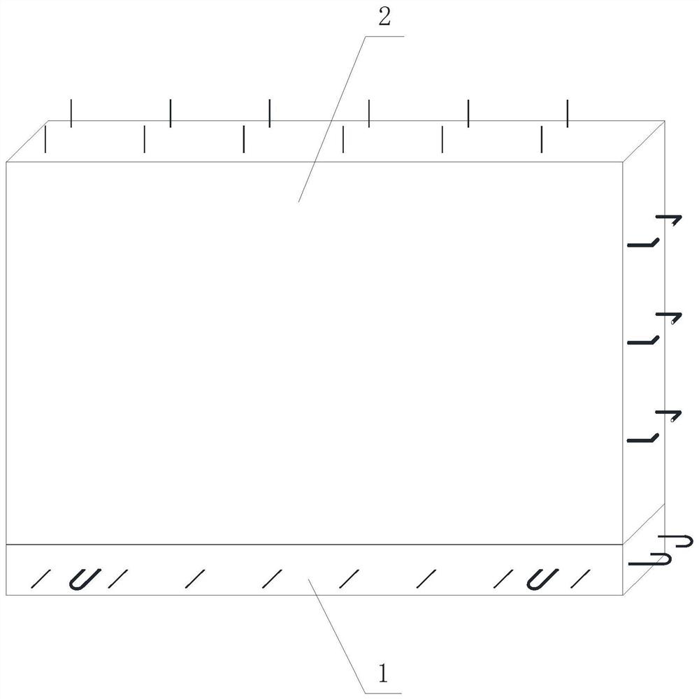
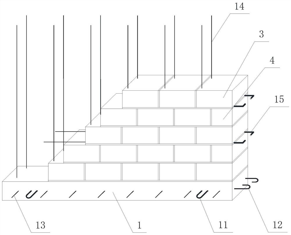
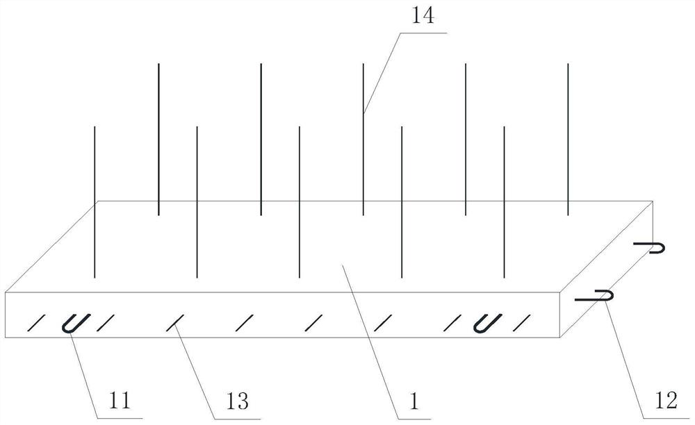
[0042] refer to Figure 1 to Figure 10 , The present invention provides a self-insulating prefabricated wall, including a base 1 and a masonry fixed on the base 1, and the structures of the base and the masonry will be described in detail below.

[0043] The base 1 is used as a support carrier and is made of concrete pouring. The length of the base (left and right direction) is 1.5m-3.5mm, the width (front and rear direction) is 15-30cm, and the height (vertical direction) is 8cm-20cm. 1 is provided with a steel bar support, and the steel bar support includes a third steel bar 11 parallel to the width direction of the base 1, a fourth steel bar 12 parallel to the length direction of the base 1, and a fifth steel bar 13 parallel to the third steel bar 11, the third steel bar 11 are at least two and arranged symmetrically left and right, the fourth stee...


PUM


Abstract

The invention provides a self-heat-insulation prefabricated wall. The self-heat-insulation prefabricated wall comprises a base and a brickwork, wherein the base is formed by pouring concrete, and a steel bar support is arranged in the base; the brickwork is fixed on the base and is built by porous bricks and/or hollow bricks, first steel bars parallel to the length direction of the brickwork and second steel bars parallel to the height direction of the brickwork are arranged in the brickwork, and the lower ends of the second steel bars are fixedly connected with the base; and the two ends of the first reinforcing steel bars and the upper ends of the second reinforcing steel bars extend out of the brickwork. The self-heat-insulation prefabricated wall is compact in structure, low in manufacturing cost and transportation cost, convenient to assemble, high in strength and good in heat insulation effect, the house building efficiency is greatly improved, the cost is reduced, and the self-heat-insulation prefabricated wall is suitable for batch production and use and has a large application market.

Description

technical field [0001] The invention relates to a wall body module, in particular to a self-insulation prefabricated wall body. Background technique [0002] The prefabricated wall is to prefabricate the wall required for the building in the factory, and then assemble the wall on site, such as a framed public building. Compared with cast-in-place concrete construction, the prefabricated wall assembly construction has a faster construction speed and a shorter construction period. At the same time, the wall can be repeatedly disassembled and reinstalled later, which saves construction costs. [0003] However, the traditional prefabricated wall adopts the form of concrete pouring. It is necessary to make a mold cavity of the corresponding size first, install steel bars in the mold cavity, and then fill it with concrete. During production, the mold cavity needs to be formed together. After the concrete is bonded, the mold is removed. It is time-consuming and laborious, and the ...

Claims


Application Information

Patent Timeline
Patent Type & Authority Applications(China)
IPC IPC(8): E04B2/00E04B2/20E04C1/40E04B2/26
CPCE04B2/00E04B2/20E04B2/26E04B2002/0289E04C1/40
Inventor 金亚敏俞露曦顾克大顾成兵陈昕
Owner 上海萌砖节能材料科技有限公司
Why Eureka
Try Eureka