Al technical title is built by PatSnap Al team. It summarizes the technical point description of the patent document.
A bypass cable and automatic laying technology, which is applied to cable laying equipment, winding strips, thin material handling, etc., can solve the problems of time-consuming and labor-intensive laying-out process, single high-paying-out method, poor emergency response capacity, etc., and achieve The effect of reducing manpower output, saving manpower, and easy disassembly and replacement
Active Publication Date: 2020-11-03
广州德晟电力科技有限公司
View PDF11 Cites 5 Cited by
Summary
Abstract
Description
Claims
Application Information
AI Technical Summary
This helps you quickly interpret patents by identifying the three key elements:
Problems solved by technology
Method used
Benefits of technology
Problems solved by technology
[0004] In order to overcome the above-mentioned defects of the prior art, an embodiment of the present invention provides an all-terrain bypass cable automatic laying vehicle. The technical problem to be solved by the present invention is: the bypass cable laying method is usually adopted in the existing bypass cable without power failure operation , a lot of manpower is invested, and the requirements for leveling the ground are high. The method of setting out the line is single, and the process of setting out the line is time-consuming and laborious. Generally, the bypass operation requires more than 8 hours of working time, and the problem of poor emergency response capacity
Method used
Image
Click on the blue label to locate the original text in one second.
Reading with bidirectional positioning of images and text.
Examples
Embodiment Construction
[0029] The following will clearly and completely describe the technical solutions in the embodiments of the present invention with reference to the accompanying drawings in the embodiments of the present invention. Obviously, the described embodiments are only some of the embodiments of the present invention, not all of them. Based on the embodiments of the present invention, all other embodiments obtained by persons of ordinary skill in the art without making creative efforts belong to the protection scope of the present invention.
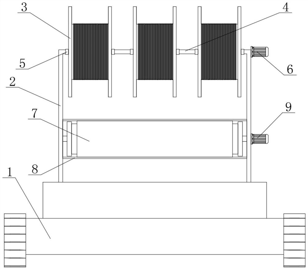
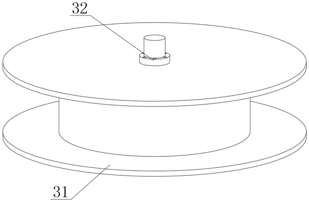
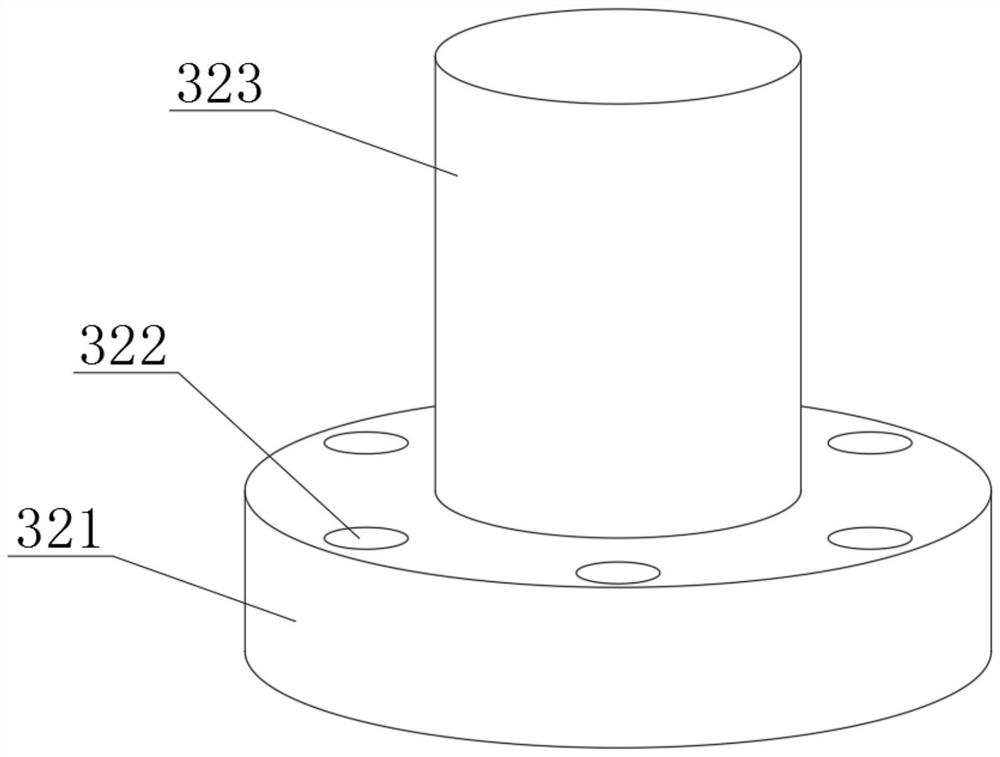
[0030] The present invention provides an all-terrain bypass cable automatic laying vehicle, comprising a driving vehicle 1, two supporting frames 2 are fixed on the top of the driving vehicle 1, and three cable take-up reels 3 are arranged on the top of the supporting frame 2, A connecting column 4 is arranged between the adjacent said cable take-up reels 3, and a fixing member 5 is arranged between said connecting column 4 and the support frame 2...
PUM
Abstract
The invention discloses an all-terrain bypass cable automatic laying vehicle, and particularly relates to the field of cable laying. The vehicle comprises a driving vehicle, two supporting frames arefixedly arranged at the top of the driving vehicle, three cable take-up reels are arranged at the top ends of the supporting frames, and a connecting column is arranged between every two adjacent cable take-up reels;fixing pieces are arranged between the connecting column and the cable take-up reel and between the supporting frame and the cable take-up reel. The vehicle is controlled to run and the cable take-up reel is controlled to unwind and wind cables and moisture-proof cloth in a wireless remote control mode, three bundles of cables are loaded on the cable take-up reel on the running vehicle, each bundle of cable bundles can be easily disassembled and replaced, and the cable bundles are installed on the running vehicle and can be driven by the first servo motor to adjust the releasespeed; therefore, the rotation number of the cable take-up reel is adjusted according to laying requirements, the cable release speed is increased, manpower output can be reduced, three-phase circuitlaying can be conducted through single-pass work, operation of constructors is facilitated, the crawler wheels are used for bypass operation without power failure, and it is guaranteed that the traveling vehicle adapts to laying of various terrains.
Description
technical field [0001] The invention relates to the technical field of cable laying, and more specifically, the invention relates to an all-terrain bypass cable automatic laying vehicle. Background technique [0002] Cables include power cables, control cables, compensation cables, shielded cables, high-temperature cables, computer cables, signal cables, coaxial cables, fire-resistant cables, marine cables, mining cables, aluminum alloy cables, etc. Cables are composed of single-strand or multi-strand wires and insulating layers, etc., and are used to connect circuits, electrical appliances, etc. It is widely used because of its good insulation performance, high chemical stability, no rust, no aging, and adaptability to harsh environments. Cable laying refers to the process of cables reaching electrical equipment or another distribution box after they come out of the distribution box. routing method. For example, concealed or exposed laying along the ground, along the wall...
Claims
Application Information
Patent Timeline
Application Date:The date an application was filed.
Publication Date:The date a patent or application was officially published.
First Publication Date:The earliest publication date of a patent with the same application number.
Issue Date:Publication date of the patent grant document.
PCT Entry Date:The Entry date of PCT National Phase.
Estimated Expiry Date:The statutory expiry date of a patent right according to the Patent Law, and it is the longest term of protection that the patent right can achieve without the termination of the patent right due to other reasons(Term extension factor has been taken into account ).
Invalid Date:Actual expiry date is based on effective date or publication date of legal transaction data of invalid patent.