Integrated deep-sea mining vehicle

A deep-sea mining and integrated technology, applied in mining minerals, special mining, earth square drilling, etc., can solve the problems of low economy and reliability, increasing the difficulty and cost of system deployment and recovery, and high requirements for cooperation between mining workshops. Achieve effects that are conducive to regeneration, reduce the impact on the marine environment, and ensure continuity

Active Publication Date: 2020-11-06
CENT SOUTH UNIV
View PDF8 Cites 12 Cited by
  • Summary
  • Abstract
  • Description
  • Claims
  • Application Information

AI Technical Summary

Problems solved by technology

The scheme adopts a separate mining method, which has particularly high requirements for the cooperation of the mining workshop. At the same time, t...

Method used


Image

  • Integrated deep-sea mining vehicle
  • Integrated deep-sea mining vehicle
  • Integrated deep-sea mining vehicle

Examples


Embodiment 1

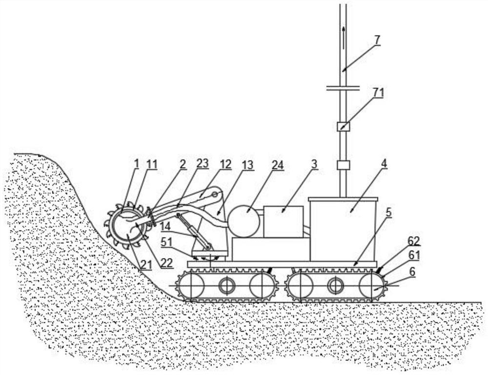
[0025] Such as figure 1 As shown, the integrated deep-sea mining vehicle of this embodiment adopts a four-crawler-type traveling mechanism 6, and the power is provided by cables lowered by a sea surface support ship. A stepped frame 5 is installed on the traveling mechanism 6 to support the cutting device 1 , the collecting device 2 , the hydrocyclone 3 , the feed bin 4 , the lifting device 7 and other equipment. A turntable 51 is arranged at the front end of the vehicle frame 5, and the turntable 51 is powered by a hydraulic motor. Described cutting device 1 comprises wheel-shaped cutting head 11, boom 12, support 13 and hydraulic cylinder 14, and described cutting head 11 is installed on an end of boom 12, and the other end of described boom 12 is connected with support. The top of 13 is hinged, and described support 13 is installed on the turntable 51, and the piston rod of described hydraulic cylinder 14 links to each other with the middle part of boom 12, and cylinder ba...

Embodiment 2

[0031] Compared with embodiment 1, the difference of this embodiment is: as Figure 4As shown, the bottom of the ore suction chamber 21 is provided with a material receiving plate 27 that slides up and down with the ore suction chamber 21, and the material receiving plate 27 is connected to the bottom of the ore suction chamber through a telescopic structure. Specifically, the telescopic structure includes a rod body 28 and a pipe body 29 that are sealed and slidingly socketed. The top of the rod body 28 is connected to the receiving plate 27, and the bottom is connected to the inner wall of the pipe body 29 through a spring 210. The enclosed space can avoid spring corrosion. . The pipe body 29 is connected to the bottom of the ore suction chamber 21 . When a blockage is formed due to phenomena such as bridge arches, because the bucket 16 continuously pours mineral materials into the ore suction chamber 21, the mineral material carried on the material receiving plate 27 will ...


PUM


Abstract

The invention discloses an integrated deep-sea mining vehicle which includes a walking mechanism, a vehicle frame, a cutting device, a collecting device, a hydrocyclone, a material bin, and a liftingdevice. The cutting device includes a cutting head, a movable arm, a bracket and a hydraulic cylinder, the cutting head is installed at one end of the movable arm, the cutting head is driven to rotateby a driving device, the other end of the movable arm is hinged to the top of the bracket, a piston rod of the hydraulic cylinder is connected to the middle part of the movable arm, and a cylinder barrel is hinged to the bottom of the bracket. The collecting device includes an ore suction chamber, a hard tube, a hose and a centrifugal pump which are in communication in sequence, the ore suction chamber is arranged inside the cutting head, the discharge end of the centrifugal pump is in communication with the hydrocyclone, and the hydrocyclone is in communication with the material bin througha pipeline. The integrated deep-sea mining vehicle integrates the mining processes such as leveling, cutting, collection, and separation, economical, efficient, reliable, and continuous deep-sea mining operations are realized, and the integrated deep-sea mining vehicle is suitable for large-scale mining of seabed polymetallic sulfide ores.

Description

technical field [0001] The invention relates to the technical field of deep sea mining equipment, in particular to an integrated deep sea mining vehicle. Background technique [0002] Deep-sea polymetallic sulfide deposits are rich in metal elements such as gold, silver, copper, and lead, and are mainly distributed in mid-ocean ridges and seabed activities frequently at 1500-4000 on the seabed. The ore deposit is formed by the combination of hydrothermal eruption and cold water from the crater. Its occurrence state is rough chimney-shaped stones on the seabed, and the thickness of the formation on the seabed can reach several meters or even more than ten meters. It has great mining prospects. Seabed mining equipment works in a seawater environment of several thousand meters, the conditions are very harsh, mining is difficult, and the investment is huge. Therefore, it is necessary to propose a feasible and cost-effective mining plan. At the same time, in the process of marin...

Claims


Application Information

Patent Timeline
IPC IPC(8): E21C50/00
CPCE21C50/00
Inventor 李艳戴欢梁科森李皓
Owner CENT SOUTH UNIV
Why Eureka
Try Eureka