Strain pickup magnetic adsorption optical cable

A magnetic adsorption and optical cable technology, applied in the direction of light guides, optics, optical components, etc., can solve problems such as low coupling efficiency, large loss of seismic wave signals, and reduced optical fiber sensitivity, so as to improve response ability, improve pickup ability, and reduce energy loss. Effect

Active Publication Date: 2020-11-06
UNIV OF ELECTRONICS SCI & TECH OF CHINA +1
View PDF5 Cites 2 Cited by
  • Summary
  • Abstract
  • Description
  • Claims
  • Application Information

AI Technical Summary

Problems solved by technology

[0004] The purpose of the present invention is to address the above-mentioned deficiencies in the prior art, and provide a strain-picking magnetic adsorption optical cable to solve the problem that the existing optical fiber distributed acoustic wave sensing technology cannot push the optical cable against the inner wall of the casing, causing the seismic wave signal In the process of transmitting the tube to the optical cable, it needs to be transmitted to the optical cable through mud, air, and water. During this process, the seismic wave signal is greatly lost, resulting in low coupling efficiency of external sound waves or vibration energy to the optical fiber strain, thereby reducing the optical fiber to the outside world. The sensitivity of acoustic wave and vibration perception limits the detection range of optical fiber

Method used


Image

  • Strain pickup magnetic adsorption optical cable
  • Strain pickup magnetic adsorption optical cable
  • Strain pickup magnetic adsorption optical cable

Examples


Embodiment 1

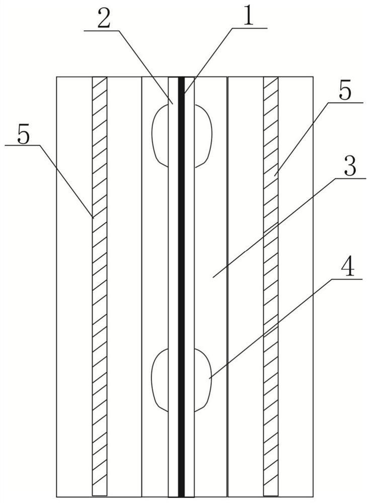
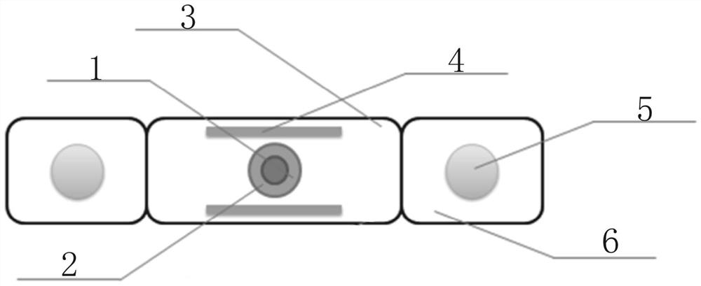
[0026] Embodiment 1, reference figure 1 with figure 2 , a strain-picking magnetic adsorption optical cable of this solution, including a tight-packed optical fiber 1 , an optical fiber outer sheath 2 , a protective layer 3 , an adsorption element 4 and a strengthening unit 6 .

[0027] Among them, the outer surface of the tight-packed optical fiber 1 is closely attached to the outer sheath 2 of the optical fiber; the type of optical fiber in the tight-packed optical fiber 1 is a single-mode optical fiber, and the number of optical fibers is at least one; the sleeve of the tight-sleeved optical fiber is made of a polymer material , You can choose polyvinyl chloride, low-smoke halogen-free polyolefin, nylon, elastomer and other materials.

[0028] The type of fiber in the tight tube fiber is single-mode fiber, the number of fiber is 1, the type of fiber is ordinary communication fiber, and the type of fiber can also choose grating array fiber.

[0029] The outer diameter of t...

Embodiment 2

[0036] Embodiment 2, refer to image 3 , a kind of strain pick-up magnetic absorption optical cable of this scheme, comprises tight-wrapped optical fiber 1, optical fiber outer sheath 2, protective layer 3, adsorption element 4 and reinforcing core 5; 2.

[0037] Among them, several reinforcing cores 5 are closely arranged along the outside of the outer sheath 2 of the optical fiber, which are used to improve the structural strength of the tightly wrapped optical fiber and the outer sheath of the optical fiber, wherein the adsorption units 4 are arranged in the protective layer at certain intervals, and the protective layer Several reinforcing cores are set outside; among them, one of the reinforcing cores can preferably be replaced by a tight-packed optical fiber, wherein the structure of the tight-packed optical fiber is that a bare optical fiber is arranged in a capillary steel pipe, and in this structure, several reinforced cores arranged outside the protective layer One ...

Embodiment 3

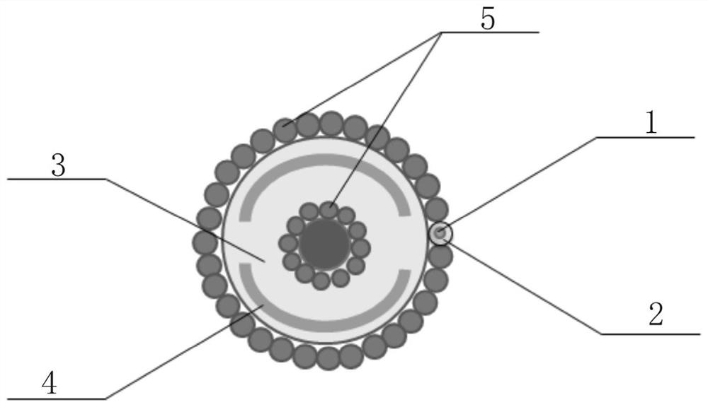
[0042] Embodiment 3, refer to Figure 4 , 5 , a strain-picking magnetic adsorption optical cable of this solution, including a tight-packed optical fiber 1 , an optical fiber outer sheath 2 , a protective layer 3 , an adsorption element 4 and a reinforcing core 5 .

[0043]A groove 7 is arranged on one side of the protective layer 3, and the tightly wrapped optical fiber 1 and the outer sheath 2 of the optical fiber are arranged in the groove 7, and the groove 7 can be rectangular, circular or elliptical. The advantage of this structure setting is that on the basis of the existing optical cable structure, different optical cable types and performances can be realized by replacing the tight-wrapped optical fiber 1 and the optical fiber outer sheath 2, which improves the application ability of the optical cable in different terrains and different well conditions.

[0044] The adsorption element 4 is arranged in the protective layer 3, and the adsorption element 4 is distributed...


PUM

PropertyMeasurementUnit
diameteraaaaaaaaaa
thicknessaaaaaaaaaa

Abstract

The invention discloses a strain pickup magnetic adsorption optical cable, which comprises a tightly packaged optical fiber. The outer surface of the tightly packaged optical fiber is closely providedwith an optical fiber outer sheath. A protective layer is arranged on the outer side of the optical fiber outer sheath, a plurality of adsorption elements wrapping the outer side of the optical fiberouter sheath are arranged in the protective layer, and the adsorption elements are distributed at intervals in the length direction of the tightly-packaged optical fiber. The adsorption element is tightly attached to the inner wall of the sleeve, external earthquake sound waves can directly act on the sensing optical cable after being transmitted to the sleeve, energy loss in the process from thesleeve to the optical cable is reduced, the weak earthquake signal pickup capacity of the optical cable is improved, and the weak earthquake signal response capacity of the system is improved. The tightly packaged optical fiber, the optical fiber outer sheath, the adsorption element and the protection layer are tightly attached without any gap, so that most of sound wave signals acting on the optical cable are loaded to the optical fiber, attenuation of sound wave energy by an ointment layer and an air layer in the optical cable is reduced, and the weak signal pickup capability of the opticalfiber is improved.

Description

technical field [0001] The invention belongs to the technical field of optical fiber sensing, and in particular relates to a strain-picking magnetic adsorption optical cable. Background technique [0002] Optical Distributed Acoustic Sensing (DAS) technology has become an important detection technology for oil and gas field exploration and development, and production operation status monitoring. It uses optical fiber to perform dual functions of signal transmission and sensing. One end of the optical cable is connected to the test instrument, and the continuous distribution of the sound field along the optical fiber can be detected. Compared with the existing cable-connected geophone testing technology, the optical fiber distributed acoustic wave sensing technology has the advantages of wide frequency range, no electromagnetic interference, simple structure, easy layout, long test distance, etc., and gradually replaces the geophone detection technology. [0003] In the proc...

Claims


Application Information

Patent Timeline
Patent Type & Authority Applications(China)
IPC IPC(8): G02B6/44
CPCG02B6/443G02B6/4432
Inventor 冉曾令李凯王熙明安树杰张仁志饶云江
Owner UNIV OF ELECTRONICS SCI & TECH OF CHINA
Why Eureka
Try Eureka