
SCR denitration device ammonia injection flow adjusting method based on model prediction

A technology of model prediction and adjustment methods, which is applied in the direction of flow control of electric devices, separation methods, flow control, etc., can solve the problems of low system response rate, excessive discharge, large pure measurement delay, etc., to solve the problem of large measurement delay and reduce Time cost, the effect of improving the convergence speed

Active Publication Date: 2020-11-06
海南创实科技有限公司
View PDF11 Cites 7 Cited by
  • Summary
  • Abstract
  • Description
  • Claims
  • Application Information

AI Technical Summary

Problems solved by technology

[0005] (1) The concentration of nitrogen oxides at the inlet and outlet is measured by the CEMS system. The sampling pipeline of the CEMS system is relatively long, resulting in a relatively large pure delay in measurement, and the measured value has a delay of 2-3 minutes;
[0006] (2) The existing CEMS system uses single-point sampling measurement, so the measurement data cannot represent the average concentration of the entire cross-section;
[0007] (3) PID control is adopted, and the PID parameters will not be changed after the initial setting. Therefore, when the operating conditions of the unit load change, the denitrification system is not adjusted in time, and excessive emissions are prone to occur;
[0008] In order to ensure emission standards, the power plant operators set the PID parameter settings very low, resulting in excessive ammonia injection, large overshoot of the control system, and low system response rate
It not only wastes reducing agent, but also increases the risk of subsequent equipment blockage

Method used


Image

  • SCR denitration device ammonia injection flow adjusting method based on model prediction
  • SCR denitration device ammonia injection flow adjusting method based on model prediction
  • SCR denitration device ammonia injection flow adjusting method based on model prediction

Examples


Embodiment Construction

[0046] The following will clearly and completely describe the technical solutions in the embodiments of the present invention with reference to the accompanying drawings in the embodiments of the present invention. Obviously, the described embodiments are only some, not all, embodiments of the present invention. Based on the embodiments of the present invention, all other embodiments obtained by persons of ordinary skill in the art without making creative efforts belong to the protection scope of the present invention.

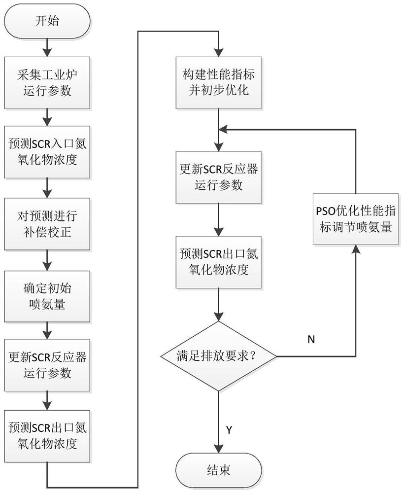
[0047] figure 1 It is the schematic diagram of the existing PID control system, figure 2 Schematic diagram of the method for adjusting the ammonia injection flow rate of the SCR denitrification device based on model prediction provided by the present invention, image 3 For the SCR ammonia injection flow regulation flow chart of the present invention, Figure 4 It is a schematic diagram of an industrial furnace combustion prediction model and a multivariabl...


PUM


Abstract

An SCR denitration device ammonia injection flow adjusting method based on model prediction comprises: firstly, training and obtaining an industrial furnace combustion prediction model and a multivariable prediction control model, then obtaining a predicted value of the nitrogen oxide concentration of an inlet of an SCR reactor through prediction, and then determining the initial ammonia injectionamount; then, according to the corrected prediction value of the concentration of the nitrogen oxide at the inlet of the SCR reactor, multivariable parameters of the SCR reactor and the multivariableprediction control model, predicting the concentration of nitric oxide at the outlet of the SCR reactor, constructing a performance index function according to the predicted value, the measured value, the set value and the ammonia spraying amount of the concentration of nitric oxide at the outlet of the SCR reactor, and then conducting preliminary optimization of the ammonia spraying amount; andfinally, updating the actual ammonia injection amount of the SCR reactor by using the preliminary optimization result of the ammonia injection amount, taking the actual ammonia injection amount as theoptimal position initial value of the next PSO algorithm, predicting the concentration of nitrogen oxide at the outlet of the SCR reactor, returning to the step 7, continuing to optimize the performance index by using the PSO algorithm, and repeating the iteration in this way.

Description

technical field [0001] The invention relates to the technical field of flue gas out-of-stock industrial furnaces, in particular to a method for regulating the flow rate of ammonia injection in an SCR denitrification device based on model prediction. Background technique [0002] With the continuous acceleration of social and economic development, my country's nitrogen oxide emissions continue to increase, so it is facing huge pressure to reduce nitrogen oxide emissions. SCR denitrification technology has been widely used in domestic coal-fired power plants, and it has the advantages of high denitrification efficiency and mature technology. [0003] At present, the SCR denitrification device adopts the flue gas online monitoring system (Continuous Emission Monitoring System, CEMS) to collect the flue gas components at the inlet of the denitrification reaction catalyst bed, and then performs proportional-integral-derivative (Proportion Integration Differentiation, PID) feedbac...

Claims


Application Information

Patent Timeline
IPC IPC(8): G05D7/06B01D53/86
CPCG05D7/0635B01D53/8696B01D53/8625
Inventor 蔡晨晓朱茂旗王丽娜赵博
Owner 海南创实科技有限公司
Learn More