A real-time monitoring system for linear motor with double loop network

A linear motor and real-time monitoring technology, applied in general control systems, control/regulation systems, propulsion systems, etc., can solve the problems of large influence of motor performance parameters, high requirements for real-time monitoring, and high requirements for monitoring reliability, and achieve anti-electromagnetic The effect of strong interference ability, small size and high reliability

Active Publication Date: 2012-11-21
NAVAL UNIV OF ENG PLA
View PDF0 Cites 3 Cited by
  • Summary
  • Abstract
  • Description
  • Claims
  • Application Information

AI Technical Summary

Problems solved by technology

Since the linear motor and related auxiliary systems need to monitor a large amount, and the electromagnetic launch of the aircraft is a short-term repetitive process, it only takes less than 2 seconds to complete the whole process of ejecting an aircraft, so the real-time monitoring requirements are high; the linear motor The temperature of the motor has a great influence on the performance parameters of the motor. The monitoring sensor is in a complex electromagnetic environment, and there are factors such as process uncertainty and external interference. A fault in one place may lead to the paralysis of the entire system and control failure, which will have serious consequences. , so the reliability of monitoring is high; at the same time, the internal space of the ship is limited, the arrangement of electronic equipment is complicated, and maintenance is difficult, so the easy maintainability of the monitoring system is put forward very high requirements

Method used


Image

  • A real-time monitoring system for linear motor with double loop network
  • A real-time monitoring system for linear motor with double loop network
  • A real-time monitoring system for linear motor with double loop network

Examples


Embodiment Construction

[0026] The present invention will be further described below in conjunction with the accompanying drawings and embodiments.

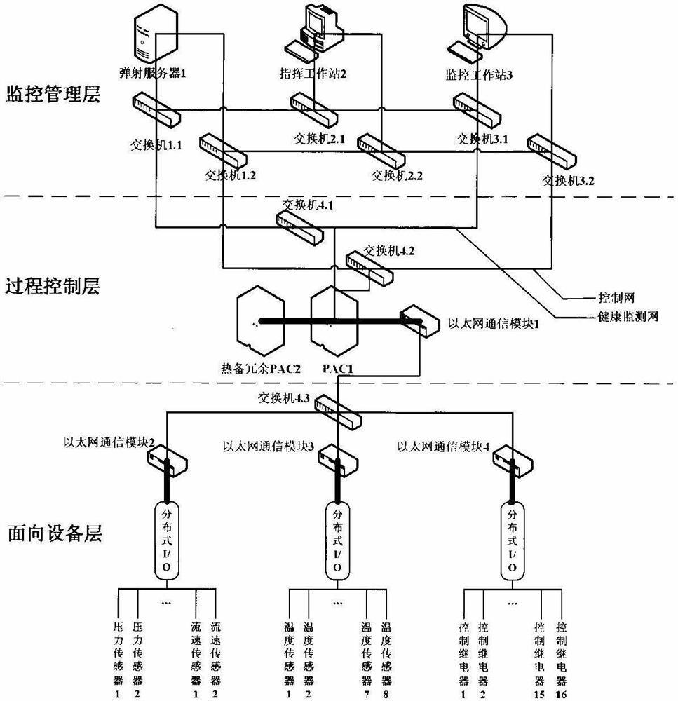
[0027] exist figure 1 Among them, the linear motor real-time monitoring system is mainly divided into three layers: monitoring management layer, process control layer, and device-oriented layer. The diagram is now explained according to the signal flow direction of the monitoring data from the bottom layer to the top layer. The sensor network facing the equipment layer collects the monitoring data of the linear motor, such as the stator temperature of the linear motor, the temperature of the mover, the flow rate of the water cooling system of the linear motor, and other analog quantities. The sensor outputs a current of 4 to 20 mA and inputs it to the distributed I / O. In the analog input module 1794-IB16D or the temperature input module 1794-IR8, the switching value such as the limit position switch of the linear motor is converted into a switching lev...


PUM


Abstract

The invention provides a real-time monitoring system for linear motors with dual networks. The monitoring system includes a three-layer structure of a monitoring management layer, a process control layer, and a device-oriented layer. The monitoring management layer includes: an ejection server, a monitoring workstation, a command workstation, and a process The control layer includes programmable automation controllers, redundant hot standby controllers, and network communication modules, and the device-oriented layer includes network communication modules, distributed I / O, and sensor networks for linear motors. Among them, a dual-network structure is adopted between the monitoring management layer and the process control layer. Both the control network and the health monitoring network use 1000Mbps optical fiber Ethernet. The control network transmits control commands and control feedback signals or comprehensive health status signals, and the health monitoring network transmits a large number of sensors. Monitoring data, dual networks work in isolation from each other. The process control layer and the device-oriented layer adopt 100Mbps Ethernet communication. The system is a real-time monitoring system of linear motor system that meets the requirements of real-time, reliability and maintainability.

Description

technical field [0001] The invention relates to linear motor system monitoring, in particular to a real-time monitoring system for linear motors. Background technique [0002] On the future aircraft carriers and large ships of the Chinese Navy, electric propulsion systems, large-capacity regional power distribution systems, electromagnetic aircraft launch systems (EMALS), high-performance weapons (such as electromagnetic rail guns, laser weapons, pulse weapons, microwave weapons, etc.) Equal sub-systems have become an important symbol of ship modernization, and the high reliability of these sub-systems is a key system to ensure and improve the combat technical indicators and performance of equipment. [0003] Existing real-time monitoring systems are mainly used in the field of industrial control, and most of them use PLC (programmable logic controller) as the monitoring and processing core, ordinary computers as the upper computer, and sensor networks as the bottom layer. ...

Claims


Application Information

Patent Timeline
IPC IPC(8): G05B15/00H04L12/28H02K41/02
Inventor 饶金马名中张明元沈建清李维波江汉红刘德志马伟明
Owner NAVAL UNIV OF ENG PLA
Why Eureka
Try Eureka