Waste gas treatment device for screw extruder

A waste gas treatment device and screw extruder technology, applied in the direction of climate sustainability, greenhouse gas reduction, combustion methods, etc., can solve the problems of not making good use of the heat of combustion waste gas, affecting the living environment of residents, affecting air quality, etc. , to avoid direct emission of waste gas, improve energy utilization rate, and ensure the effect of dust removal

Pending Publication Date: 2020-11-10
NANTONG HUILI RUBBER
View PDF2 Cites 1 Cited by
  • Summary
  • Abstract
  • Description
  • Claims
  • Application Information

AI Technical Summary

Problems solved by technology

Therefore, the waste gas discharged from the regeneration process contains carbon dioxide, H 2 S, benzene, toluene, xylene, non-methane total hydrocarbons and other pollutants, as well as water vapor, a small amount of rubber powder particles, etc., the direct emission of exhaust gas will affect the surrounding environment and have a foul smell
[0003] The Chinese patent with the authorized announcement number CN209519586U discloses a waste tire refining waste gas desulfurization and dust removal equipment. The patent solves the problem that the waste gas discharged by the existing technology contains a large amount of Sulfur, acid, dust and other harmful components, the emissions are not up to standard, which affects the living environment of residents and air quality problems, but the effect of spraying to treat exhaust gas still has certain limitations
The authorized announcement number is a waste gas treatment device disclosed in CN206285676U. Although the waste gas treatment device is processed by filtering, burning and re-filtering, most of the pollution in the waste gas is removed, and the pollution of the waste gas to the environment is greatly alleviated. , however, the exhaust gas treatment device does not make good use of the heat generated by the combustion exhaust gas in the combustion process

Method used


Image

  • Waste gas treatment device for screw extruder
  • Waste gas treatment device for screw extruder
  • Waste gas treatment device for screw extruder

Examples


Embodiment Construction

[0036] The present invention will be described in further detail below in conjunction with the accompanying drawings and embodiments. It should be understood that the specific embodiments described here are only used to explain the present invention, not to limit the present invention.

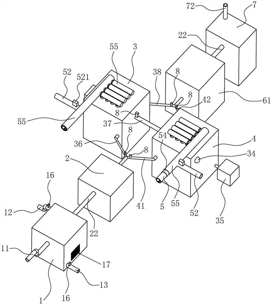
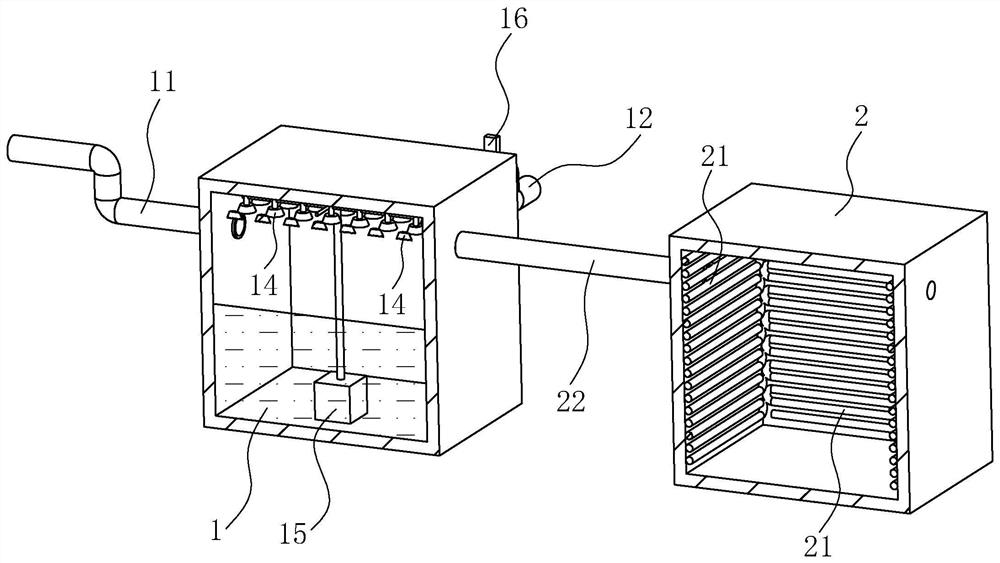
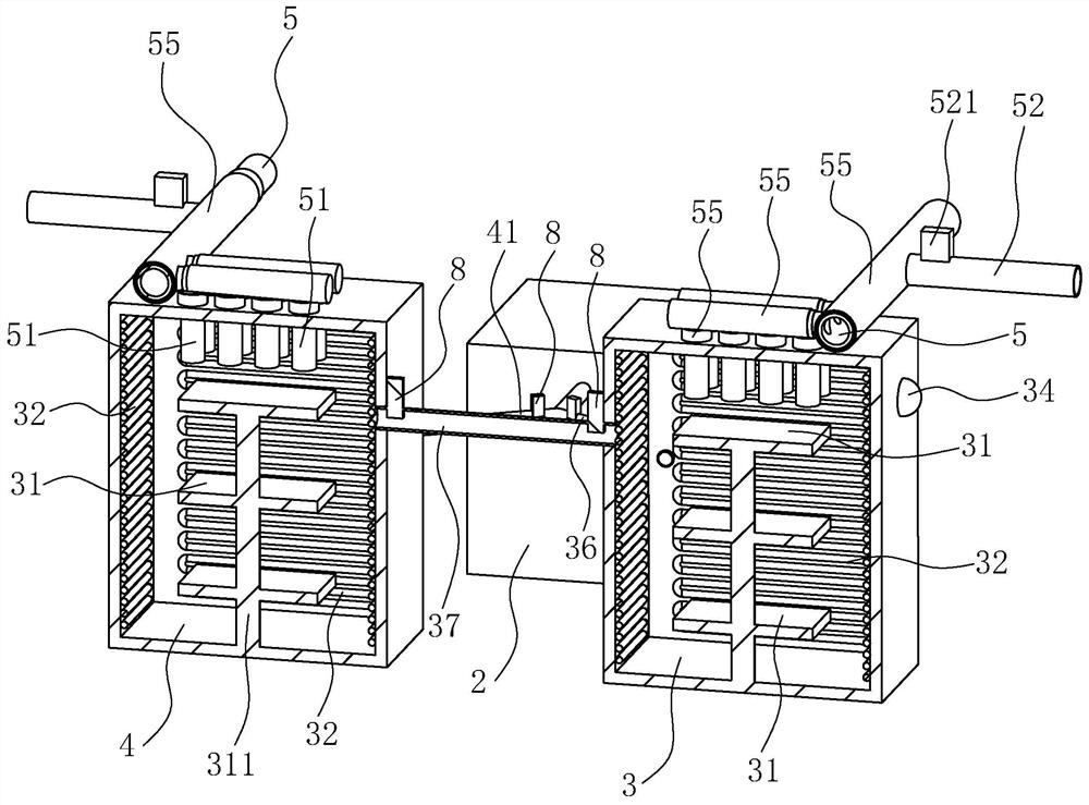
[0037] A waste gas treatment device for a screw extruder, such as figure 1 As shown, it includes spray chamber 1, preheating chamber 2, primary combustion chamber 3, water cooling box 6 (combined with Figure 6 ), dry box 7 and the secondary combustion chamber 4 that is arranged side by side with the primary combustion chamber 3 and has the same structure, the preheating chamber 2 and the water cooling box 6 are respectively located at the two sides of the primary combustion chamber 3 and the secondary combustion. Such as figure 1 As shown, the spray chamber 1 is connected with an air intake pipe 11, and the spray chamber 1 and the preheating chamber 2, the water cooling box 6 and the drying...


PUM


Abstract

The invention provides a waste gas treatment device for a screw extruder, and relates to the technical field of rubber regeneration equipment. The waste gas treatment device comprises a spraying chamber, a preheating chamber and a primary combustion chamber, wherein a pipeline for communicating the spraying chamber and the preheating chamber is arranged between the spraying chamber and the preheating chamber, and a first gas supply pipe for communicating the preheating chamber and the primary combustion chamber is arranged between the preheating chamber and the primary combustion chamber; thespraying chamber is communicated with an intake pipe, a plurality of spraying heads are arranged at the top in the spraying chamber, and a preheating electric heating pipe is arranged on the inner wall of the preheating chamber; a plurality of layers of catalytic beds arranged up and down are arranged in the primary combustion chamber, a combustion electric heating pipe is arranged on the inner wall of the primary combustion chamber, and the primary combustion chamber is further connected to a first outlet pipe. A plurality of small heat transfer pipes which are parallel to each other and arearranged above the catalytic bed at the uppermost layer are further arranged in the primary combustion chamber, and penetrate through the primary combustion chamber and are communicated with a main heat transfer pipe for connecting the small heat transfer pipes. When the device is used, waste gas can be effectively treated, waste gas emission is guaranteed to be clean and free of pollution, heat generated by waste gas combustion can be fully utilized, and the energy utilization rate is increased.

Description

technical field [0001] The invention relates to the technical field of rubber regeneration equipment, in particular to a waste gas treatment device of a screw extruder. Background technique [0002] Regenerated rubber is made of waste rubber as raw material by recycling technology. The regeneration process needs to go through a desulfurization process to change the plastic state of the waste rubber particle network structure and restore its soft rubber-like structure. Therefore, the waste gas discharged from the regeneration process contains carbon dioxide, H 2 S, benzene, toluene, xylene, non-methane total hydrocarbons and other pollutants, as well as water vapor, a small amount of rubber powder particles, etc., the direct discharge of exhaust gas will affect the surrounding environment and have a foul smell. [0003] The Chinese patent with the authorized announcement number CN209519586U discloses a waste tire refining waste gas desulfurization and dust removal equipment....

Claims


Application Information

Patent Timeline
Patent Type & Authority Applications(China)
IPC IPC(8): F23G7/07F23G5/02F23G5/033F23G5/10F23G5/16F23G5/44F23G5/46F23G5/50F23J15/06F23J15/00B01D53/26
CPCB01D53/26F23G5/02F23G5/033F23G5/10F23G5/16F23G5/44F23G5/46F23G5/50F23G7/07F23G2201/10F23G2201/60F23G2202/103F23G2202/60F23G2204/20F23G2206/20F23G2209/14F23J15/00F23J15/06Y02E20/30
Inventor 倪雪文周洪王郁辉赵勇赵建忠张国华
Owner NANTONG HUILI RUBBER
Why Eureka
Try Eureka