Rotary mixing device for glass raw materials

A technology for mixing devices and glass raw materials, which is applied to mixers, mixers with rotating stirring devices, transportation and packaging, etc., can solve the problem of single stirring direction, prevent single stirring direction, improve mixing efficiency, and simple structure Effect

Pending Publication Date: 2020-11-13
ANHUI FENGYANG HUAIHE GLASS
View PDF16 Cites 2 Cited by
  • Summary
  • Abstract
  • Description
  • Claims
  • Application Information

AI Technical Summary

Problems solved by technology

[0004] The technical problem to be solved by the present invention is to provide a rotary mixing device for glass raw materials, which rotates the materials in the mixing chamber with the blades clockwise for a while and counterclockwise for a while, so that the raw materials in the mixing chamber can be fully and efficiently mixed , to prevent single stirring direction and poor mixing effect, and improve mixing efficiency

Method used


Image

  • Rotary mixing device for glass raw materials
  • Rotary mixing device for glass raw materials
  • Rotary mixing device for glass raw materials

Examples


Embodiment 1

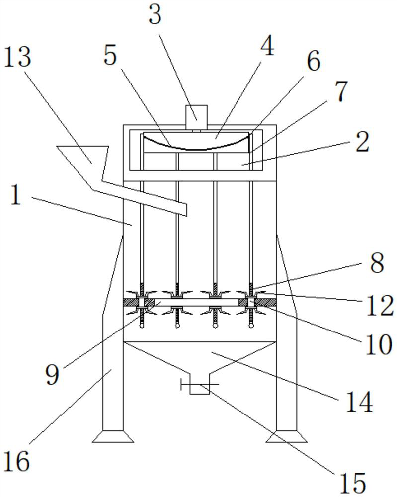
[0024] Embodiment 1: as Figure 1-3 As shown, a vortex mixing device for glass raw materials includes a mixing chamber 1, and the mixing chamber 1 is arranged in a cylindrical shape;

[0025] The top of the mixing chamber 1 is fixedly equipped with a control chamber 2, the top of the control chamber 2 is fixedly installed with a motor 3, and the bottom of the motor 3 is fixedly connected with a turntable 4, and the turntable 4 is located inside the control chamber 2, so The side wall of the turntable 4 is provided with a track 5, and the track 5 is arranged in a wave shape;

[0026] The side wall of the turntable 4 is movably clamped with several groups of pulleys 6 through the track 5, and the bottom of each group of the pulleys 6 is fixedly equipped with a connecting rod 7;

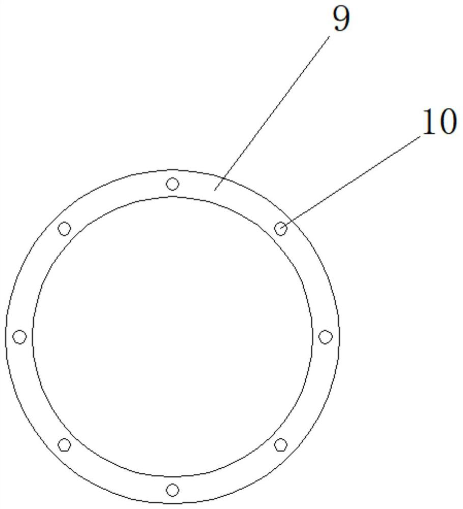
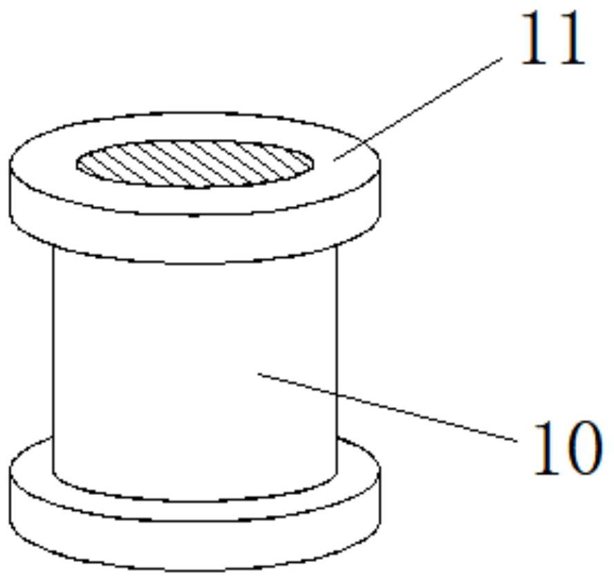
[0027] The lower part of the inner cavity of the mixing chamber 1 is fixedly equipped with a ring plate 9, and several groups of internal thread drums 10 are rotatably connected to the ring plate 9. Th...

Embodiment 2

[0039] Embodiment 2: as Figure 1-3 As shown, a vortex mixing device for glass raw materials includes a mixing chamber 1, and the mixing chamber 1 is arranged in a cylindrical shape;

[0040] The top of the mixing chamber 1 is fixedly equipped with a control chamber 2, the top of the control chamber 2 is fixedly installed with a motor 3, and the bottom of the motor 3 is fixedly connected with a turntable 4, and the turntable 4 is located inside the control chamber 2, so The side wall of the turntable 4 is provided with a track 5, and the track 5 is arranged in a wave shape;

[0041] The side wall of the turntable 4 is movably clamped with several groups of pulleys 6 through the track 5, and the bottom of each group of the pulleys 6 is fixedly equipped with a connecting rod 7;

[0042] The lower part of the inner cavity of the mixing chamber 1 is fixedly equipped with a ring plate 9, and several groups of internal thread drums 10 are rotatably connected to the ring plate 9. Th...


PUM


Abstract

The invention discloses a rotary mixing device for glass raw materials. The device comprises a cylindrical mixing bin, a control bin is fixedly mounted at the top of the mixing bin, a motor is fixedlymounted at the top of the control bin, a rotating disc is fixedly connected to the bottom of the motor and located in the control bin, and a wavy rail is formed in the side wall of the rotating disc.A plurality of sets of pulleys are movably clamped to the side wall of the rotary disc through rails, and a connecting rod is fixedly installed at the bottom of each set of pulleys. A ring plate is fixedly mounted at the lower part of the inner cavity of the mixing bin, a plurality of groups of internal thread rotary drums are rotatably connected to the ring plate, and a plurality of blades are fixedly connected to the side walls of two groups of limiting rings of each group of internal thread rotary drums; the lower part of each set of connecting rods is provided with threads, and the lowerpart of each set of connecting rods is connected to corresponding internal thread rotary drums through threads. The materials in the mixing bin can clockwise rotate along with the blades, and can anticlockwise rotate along with the blades, such that the raw materials in the mixing bin can be completely and efficiently mixed, and the mixing efficiency is improved.

Description

Technical field: [0001] The invention relates to the field of glass processing, in particular to a whirling mixing device for glass raw materials. Background technique: [0002] Glass is an amorphous inorganic non-metallic material, generally made of various inorganic minerals (such as quartz sand, borax, boric acid, barite, barium carbonate, limestone, feldspar, soda ash, etc.) of. Its main components are silicon dioxide and other oxides. The chemical composition of ordinary glass is Na2SiO3, CaSiO3, SiO2 or Na2O·CaO·6SiO2, etc. The main component is silicate double salt, which is an amorphous solid with irregular structure. Widely used in buildings, used for wind and light transmission, belongs to the mixture. There are also colored glass that is mixed with certain metal oxides or salts to show color, and tempered glass made by physical or chemical methods. Sometimes some transparent plastics (such as polymethyl methacrylate) are also called plexiglass. [0003] Durin...

Claims


Application Information

Patent Timeline
IPC IPC(8): B01F7/18B01F15/00B01F15/02
CPCB01F27/85B01F27/90B01F35/332B01F35/43B01F35/7547
Inventor 王夕增崔强王夕亮
Owner ANHUI FENGYANG HUAIHE GLASS
Why Eureka
Try Eureka