
Micro-premixing on-duty nozzle assembly and micro-premixing combustion chamber of gas turbine

A duty nozzle and combustion chamber technology, applied in combustion chambers, continuous combustion chambers, combustion methods, etc., can solve the problems of increased tempering, self-ignition and oscillation, reduction of fuel ignition delay time, and high adiabatic flame temperature, and achieves natural frequency. Differences, enhanced proportion uniformity, uniform heat release effect

Pending Publication Date: 2020-11-13
INST OF ENGINEERING THERMOPHYSICS - CHINESE ACAD OF SCI
View PDF0 Cites 2 Cited by
  • Summary
  • Abstract
  • Description
  • Claims
  • Application Information

AI Technical Summary

Problems solved by technology

Compared with combustion engines using conventional fuels (such as natural gas, etc.), combustion engines using hydrogen-rich fuels, due to the strong fuel activity of hydrogen, especially its high flame velocity, low ignition energy and wide flammability limit increase flashback, Risk of spontaneous combustion and oscillation
Also, the high adiabatic flame temperature of hydrogen is a challenge for low NOx formation
However, hydrogenation of ordinary fuel will reduce the ignition delay time of the fuel and increase the combustion speed.
This will lead to high local temperature, high nitrogen oxides, fast flame propagation speed and easy tempering and oscillation
These properties challenge the development of advanced combustion technologies and burners for hydrogen-rich fuels

Method used


Image

  • Micro-premixing on-duty nozzle assembly and micro-premixing combustion chamber of gas turbine
  • Micro-premixing on-duty nozzle assembly and micro-premixing combustion chamber of gas turbine
  • Micro-premixing on-duty nozzle assembly and micro-premixing combustion chamber of gas turbine

Examples


Embodiment Construction

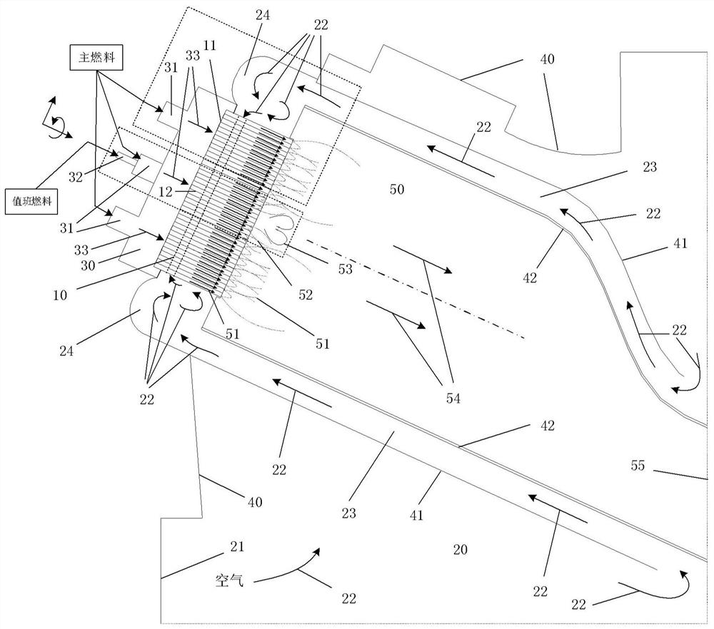
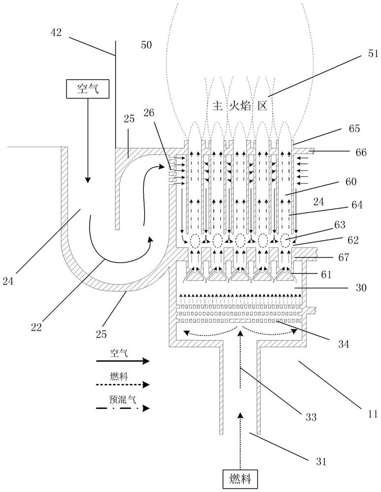
[0082] The invention provides a gas turbine micro-premix combustor to alleviate the problems of low expandability of the burner unit nozzle in the prior art, uneven mixing of fuel and air, flashback, spontaneous combustion and oscillation during operation, and at the same time alleviate the problems of nitrogen The problem of high oxide emissions.

[0083] In order to make the object, technical solution and advantages of the present invention clearer, the present invention will be further described in detail below in conjunction with specific embodiments and with reference to the accompanying drawings.

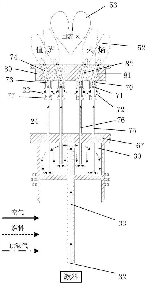
[0084] As an aspect of the present invention, a kind of micro-premix nozzle assembly on duty is provided, comprising:

[0085] The nozzle top cover is provided with multiple inclined holes;

[0086] A plurality of micro-premixing tubes, one end of the plurality of micro-premixing tubes communicates with a plurality of inclined holes on the nozzle top cover; the other end of t...


PUM

PropertyMeasurementUnit
Circumferential angleaaaaaaaaaa
Apertureaaaaaaaaaa
Major axis lengthaaaaaaaaaa

Abstract

The invention discloses a micro-premixing on-duty nozzle assembly and a micro-premixing combustion chamber of a gas turbine. The micro-premixing combustion chamber of the gas turbine comprises a flametube and a combustor, the combustor is arranged at the end part of the flame tube; the combustor comprises a plurality of combustor main nozzle areas and a combustor on-duty nozzle area; the structure of the combustor on-duty nozzle area is the same as that of the micro-premixing on-duty nozzle assembly; wherein the plurality of combustor main nozzle areas are arranged around the circumference ofthe combustor on-duty nozzle area. Compared with a traditional combustion chamber of the gas turbine, the center on-duty nozzle enables a certain backflow area to be formed near an outlet of the on-duty nozzle through space angle arrangement, and therefore the flame stabilizing effect is achieved; and meanwhile, the lengths of fuel conveying pipes on an inner ring and an outer ring of the on-dutynozzle are different, each main nozzle micro-premixing pipe can adopt different structure schemes, inherent frequency difference is achieved, the thermo-acoustic coupling probability is reduced, andthe problem of unstable combustion can be effectively avoided.

Description

technical field [0001] The invention relates to the technical field of gas turbine combustion chambers, in particular to a micro-premix duty nozzle assembly and a gas turbine micro-premix combustion chamber. Background technique [0002] Gas turbine is an efficient and clean power machine. The power generation based on gas turbine and its combined cycle has accounted for 22% of the world's total power generation, and will continue to rise in the future. In order to improve the cycle efficiency of the gas turbine, the gas initial temperature and supercharging ratio are constantly increasing. Taking heavy-duty gas turbines as an example, the initial gas temperature of F-class gas turbines is around 1650K, and the combined cycle efficiency is 57%; the initial gas temperatures of H-class and J-class gas turbines are around 1750K and 1850K, and the combined cycle efficiencies are 60% and 1850K respectively. 61%; the initial gas temperature of the next-generation gas turbine will...

Claims


Application Information

Patent Timeline
IPC IPC(8): F23R3/28
CPCF23R3/286
Inventor 邵卫卫刘勋伟刘策张哲巅肖云汉
Owner INST OF ENGINEERING THERMOPHYSICS - CHINESE ACAD OF SCI
Learn More