
Ring cooler flue gas recycling system and method

A ring cooler and flue gas technology, applied in the field of iron and steel smelting, can solve problems such as increased costs, fire hazards, and non-utilization of flue gas

Pending Publication Date: 2020-11-13
MCC NORTH (DALIAN) ENG TECH CO LTD
View PDF0 Cites 0 Cited by
  • Summary
  • Abstract
  • Description
  • Claims
  • Application Information

AI Technical Summary

Problems solved by technology

[0003] For the above-mentioned soot, the existing technology can only effectively utilize the high-temperature soot, and use the internal energy of the high-temperature soot to heat water to generate steam to drive the power generation system to generate electricity
However, due to the low calorific value of the medium-temperature flue gas, only hot water can be produced when the waste heat is reused to heat water, and steam cannot be produced.
This part of hot water can be used in the heat exchanger of the heating system in colder areas, but in the non-heating area or non-heating period, this part of the hot water needs to be cooled by another cooling device before it can be discharged normally, which increases the cost of the factory
[0004] On the other hand, some factories do not use the flue gas in the middle temperature zone and low temperature zone, but directly discharge it after dust removal.
Since the dust collector at the end of the ring cooler usually uses a bag filter, the temperature it can withstand is low, and the temperature fluctuations of the dust in the middle temperature section and the low temperature section are relatively large, often exceeding 200°C, which seriously threatens the safety of the bag filter equipment. , a fire hazard

Method used


Image

  • Ring cooler flue gas recycling system and method

Examples


Embodiment 1

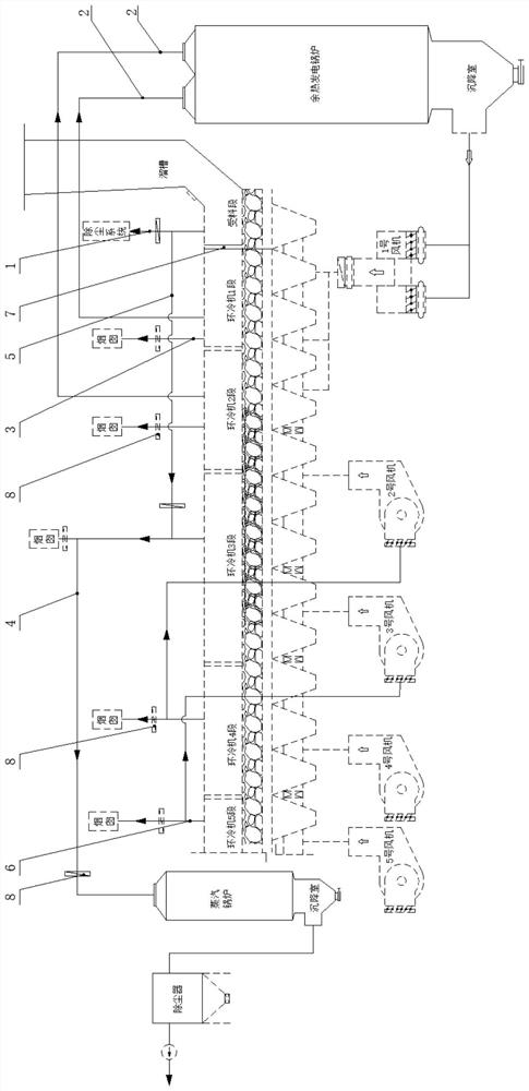
[0029] figure 1 It is a block diagram of a flue gas reuse system of an annular cooler related to an embodiment of the present invention. Shows the relationship between the various parts and links in the system.

[0030] like figure 1 As shown, in this embodiment, the annular cooler includes a chute, a material receiving section, an annular cooler 1 section, an annular cooler 2 sections, an annular cooler 3 sections, an annular cooler 4 sections, and an annular cooler 5 sections, and No. 1 fan, No. 2 fan, No. 3 fan, No. 4 fan, and No. 5 fan are arranged under the ring cooler. Among them, the 1st section of the annular cooler and the 2nd section of the annular cooler are high-temperature sections; the 3rd section of the annular cooler is a medium-temperature section; the 4th section of the annular cooler and the 5th section of the annular cooler are low-temperature sections. The No. 1 fan is used to blow cooling air into the material receiving section, the 1st section of the ...

Embodiment 2

[0045] In this embodiment, a method for reusing the flue gas of the annular cooler is provided, which is used to improve the utilization efficiency of the medium-temperature flue gas generated in the middle-temperature section of the annular cooler. The method includes:

[0046] Step S1. Collect the high-temperature flue gas generated by the material receiving section of the annular cooler, and introduce it into the flue gas collection device in the middle temperature section of the annular cooler.

[0047] Step S2, introducing the mixed flue gas in the flue gas collection device in the middle temperature section of the annular cooler into the waste heat utilization device. Preferably, the mixed flue gas is introduced into the steam boiler, and the waste heat of the mixed flue gas is used to heat the water in the boiler to generate steam.

[0048] Through this method, the calorific value of the medium-temperature flue gas collected in the flue gas collection device in the mid...


PUM


Abstract

The invention provides a ring cooler flue gas recycling system and method, and the system comprises a first flue gas collecting device which is disposed above a material receiving segment of a ring cooler so as to collect flue gas of the material receiving segment; a second flue gas collecting device which is arranged above a high-temperature segment of the ring cooler so as to collect flue gas ofthe high-temperature segment; a third flue gas collecting device which is arranged above a medium-temperature segment of the ring cooler so as to collect flue gas of the medium-temperature segment; and heat supplementing pipelines which communicate with the first flue gas collecting device and the third flue gas collecting device. By means of the device, high-temperature flue gas generated by thematerial receiving segment of the ring cooler is mixed with medium-temperature flue gas generated by the medium-temperature segment, the heat value of the flue gas generated by the medium-temperaturesegment is increased, and therefore the flue gas generated by the medium-temperature segment can be efficiently utilized.

Description

technical field [0001] The invention relates to the technical field of iron and steel smelting, in particular to a system and method for reusing flue gas from an annular cooler. Background technique [0002] The function of the ring cooler is to effectively cool the sintered hot ore unloaded from the sintering machine. The ring cooler is in the shape of a ring as a whole. When the sintered hot ore is running in the ring cooler through the trolley, the fan below blows the cold air upwards. The cold air enters the trolley through the grate plate, fully exchanges heat with the hot sintering ore inside, and then is discharged from the flue as hot flue gas. From the inlet end to the outlet section, the annular cooler is divided into: receiving section, high temperature section, medium temperature section and low temperature section according to the calorific value of the flue gas produced. The flue gas produced by it is high temperature flue gas and high temperature flue gas resp...

Claims


Application Information

Patent Timeline
Patent Type & Authority Applications(China)
IPC IPC(8): F27D17/00
CPCF27D17/001F27D17/004F27D2017/006
Inventor 韩峰李胜男王博闻姜海波
Owner MCC NORTH (DALIAN) ENG TECH CO LTD
Learn More