Current collector, pole piece and battery

A current collector and pole piece technology, which is applied in the field of batteries, can solve problems such as explosion, combustion of combustible substances such as electrolytes, and battery heating, and achieve the effects of increasing energy density, preventing thermal runaway, and reducing metal consumption

Pending Publication Date: 2020-11-13
JIANGSU ZENIO NEW ENERGY BATTERY TECH CO LTD
View PDF0 Cites 11 Cited by
  • Summary
  • Abstract
  • Description
  • Claims
  • Application Information

AI Technical Summary

Problems solved by technology

When the separator is damaged due to foreign matter inside the battery (such as particles introduced into the battery material, burrs on the pole piece, or metal lithium dendrites precipitated during battery use) or external punctures, the damaged part will be damaged twice. The positive and nega

Method used


Image

  • Current collector, pole piece and battery
  • Current collector, pole piece and battery
  • Current collector, pole piece and battery

Examples


Embodiment 1

[0057] The difference from Comparative Example 1 is:

[0058] Preparation of positive electrode sheet:

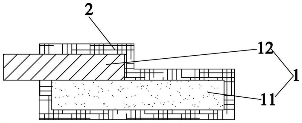
[0059] 1) Partially bond an aluminum foil (metal material layer) with a thickness of 9 μm on one surface of a PET film (polymer layer) with a thickness of 12 μm to form a base layer, and grow on the surface of the PET film and part of the aluminum foil surface by vacuum evaporation An aluminum coating (conductive layer) with a thickness of 2 μm is obtained as figure 1 The positive current collector shown;

[0060] 2) Mix NCM523 powder, SP conductive carbon black, VGCF carbon nanofiber and PTFE at a ratio of 92:3:3:2, dissolve in a solvent and stir evenly to form a positive electrode slurry, and coat the positive electrode slurry on the positive electrode current collector On the aluminum coating layer, dry and roll to form a pole piece with a thickness of 120μm, in which the coating amount of the positive electrode slurry per unit area is 17.8mg / cm 2 .

[0061] The rest...

Embodiment 2

[0063] The difference from Comparative Example 1 is:

[0064] Preparation of positive electrode sheet:

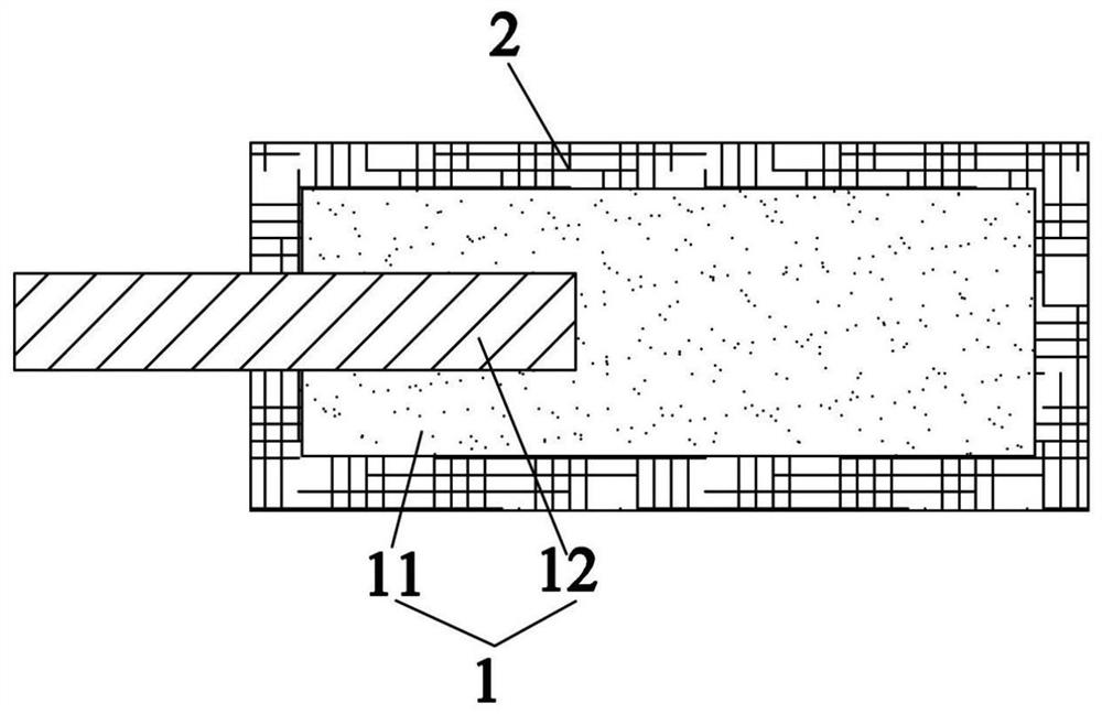
[0065] 1) Take an aluminum foil (metal material layer) with a thickness of 9 μm, and cover a part of its surface with a PET polymer layer with a thickness of 12 μm, so that the aluminum foil is partially embedded in the end of the PET polymer layer to form a base layer. The plating method grows an aluminum coating with a thickness of 2 μm on the surface of the PET polymer layer and the surface of some aluminum foils to obtain the following: figure 2 The positive current collector shown;

[0066] 2) Mix NCM523 powder, SP conductive carbon black, VGCF carbon nanofiber and PTFE at a ratio of 92:3:3:2, dissolve in a solvent and stir evenly to form a positive electrode slurry, and coat the positive electrode slurry on the positive electrode current collector On the aluminum coating layer, dry and roll to form a pole piece with a thickness of 120μm, in which the coating amount...

Embodiment 3

[0069] The difference from Comparative Example 1 is:

[0070] Preparation of positive electrode sheet:

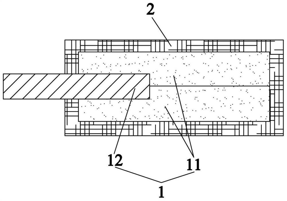
[0071] 1) A part of aluminum foil (metal material layer) with a thickness of 9 μm is sandwiched between two PET films (polymer layer) with a thickness of 5 μm to form a base layer, and the surface and part of the PET film are formed by vacuum evaporation. An aluminum coating with a thickness of 2 μm is grown on the surface of the aluminum foil to obtain the following image 3 The positive current collector shown;

[0072] 2) Mix NCM523 powder, SP conductive carbon black, VGCF carbon nanofiber and PTFE at a ratio of 92:3:3:2, dissolve in a solvent and stir evenly to form a positive electrode slurry, and coat the positive electrode slurry on the positive electrode current collector On the aluminum coating layer, dry and roll to form a pole piece with a thickness of 120μm, in which the coating amount of the positive electrode slurry per unit area is 17.8mg / cm 2 .

[0073] ...


PUM

PropertyMeasurementUnit
Thicknessaaaaaaaaaa
Thicknessaaaaaaaaaa
Thicknessaaaaaaaaaa

Abstract

The invention belongs to the technical field of batteries, and particularly relates to a current collector which comprises a substrate layer and a conductive layer. The conductive layer is arranged onthe surface of the substrate layer, the substrate layer comprises a polymer layer and a metal material layer which are connected with each other, the metal material layer is connected with the conductive layer, and part of the metal material layer is exposed out of the conductive layer. In addition, the invention also relates to a pole piece and a battery. Compared with the prior art, the currentcollector has the advantages that the metal consumption is reduced, the mass energy density of the battery is improved, the current collector can be structurally damaged at the initial stage of thermal runaway, and the thermal runaway of the battery can be prevented.

Description

technical field [0001] The invention belongs to the technical field of batteries, and in particular relates to a current collector, a pole piece and a battery. Background technique [0002] Due to its outstanding advantages such as high energy density, excellent cycle life, high working voltage, low self-discharge rate, and environmental friendliness, lithium-ion batteries have become ideal power sources for electric vehicles and energy storage. However, with the improvement of the energy density of positive and negative electrode materials, the safety of lithium-ion batteries has gradually become an important issue restricting its further promotion. [0003] High energy density, high capacity single cells are very prone to thermal runaway under abuse conditions such as overcharging, overheating, and puncture, which can lead to fire or even explosion accidents, seriously threatening the personal safety of users. The thermal runaway of batteries often originates from interna...

Claims


Application Information

Patent Timeline
IPC IPC(8): H01M4/66H01M4/134H01M4/137H01M10/0525
CPCH01M4/667H01M4/661H01M4/66H01M4/134H01M4/137H01M10/0525Y02E60/10H01M10/4235
Inventor 姚毅姜斌江柯成
Owner JIANGSU ZENIO NEW ENERGY BATTERY TECH CO LTD
Why Eureka
Try Eureka