Bridgeless double-Boost power factor correction rectifier for left-right alternating auxiliary current conversion

A power factor correction and rectifier technology, which is applied in the direction of converting AC power input to DC power output, output power conversion device, and high-efficiency power electronic conversion, etc., which can solve the problems of insufficient commutation preparation time, high voltage stress, and one-way excitation current Reset and other issues

Active Publication Date: 2020-11-13
SHANXI UNIV
View PDF6 Cites 5 Cited by
  • Summary
  • Abstract
  • Description
  • Claims
  • Application Information

AI Technical Summary

Problems solved by technology

However, there are three types of problems in the ZVT-2CI inverter series: 1) When the switch ZCS of the auxiliary circuit is turned on, only IGBT devices with small EOSS (equivalent output capacitor energy storage) can be used, and the conduction loss and EMI cannot be ignored; 2) The unidirectional reset of the excitation current leads to the large volume of the transformer magnetic core selected, and

Method used


Image

  • Bridgeless double-Boost power factor correction rectifier for left-right alternating auxiliary current conversion
  • Bridgeless double-Boost power factor correction rectifier for left-right alternating auxiliary current conversion
  • Bridgeless double-Boost power factor correction rectifier for left-right alternating auxiliary current conversion

Examples


Embodiment Construction

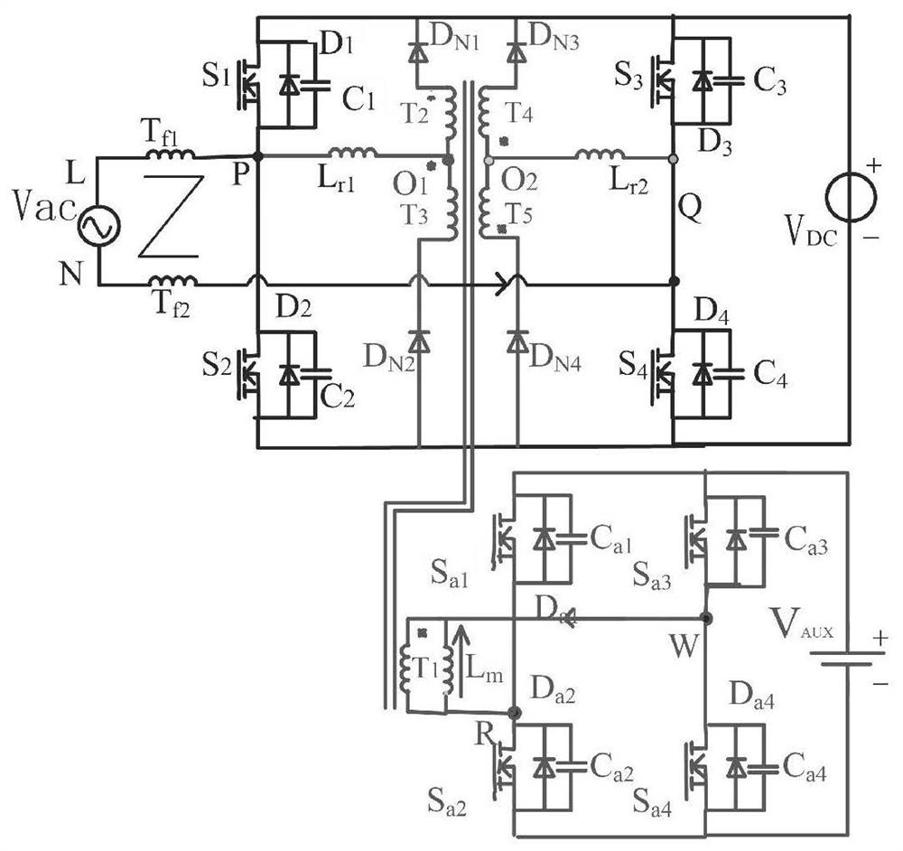
[0195] Such as Figure 1-Figure 9 As shown, the present invention provides a bridgeless dual Boost power factor correction rectifier with left and right alternate auxiliary commutation, including a first main switching tube S 1 , the second main switch S 2 , the third main switch S 3 , the fourth main switch S 4 , filter inductance T f1 , filter inductance T f2 , AC power supply V AC , DC power supply V DC , Auxiliary power supply V AUX , the first commutation diode D N1 , the second commutation diode D N2 , the third commutation diode D N3 , the fourth commutation diode D N4 , Auxiliary converter transformer primary winding T 1 , Transformer secondary winding T 2 , Auxiliary converter transformer secondary winding T 3 , Transformer secondary winding T 4 , Auxiliary converter transformer secondary winding T 5 , Resonant inductance L r1 , Resonant inductance L r2 , the first auxiliary switch tube S a1 , the second auxiliary switch tube S a2 , the third auxili...


PUM


Abstract

The invention discloses a bridgeless double-Boost power factor correction rectifier for left-right alternating auxiliary current conversion. ZVS conduction of a main loop switch and an auxiliary loopswitch can be realized. A fully-controlled switch replaces a rectifier diode of a basic bridgeless circuit, and a main loop has two charging states. Two-way reset of exciting current is achieved through the auxiliary loops working alternately, and therefore the size of a transformer magnetic core is reduced. Coupling of the secondary winding of the transformer reduces the voltage stress of the auxiliary converter diode.

Description

technical field [0001] The invention relates to the technical field of power electronic conversion, in particular to a bridgeless double Boost power factor correction rectifier with left and right alternate auxiliary commutation. Background technique [0002] Among many PFC circuits, Boost converters are widely used because of their simple structure, continuous input current and strong uniformity of characteristics. Among them, the bridgeless Boost PFC reduces the conduction loss and improves the efficiency by reducing the number of semiconductor devices on the working circuit (08003359: [8]–[21]). However, the problem of switching loss in bridgeless PFC is prominent. When the switching frequency is increased, the switching loss in the circuit will increase accordingly, especially when the circuit works in CCM, the reverse recovery current of the freewheeling diode will increase the switching Turn-on loss of the tube. In order to reduce switching loss and dynamic switching...

Claims


Application Information

Patent Timeline
IPC IPC(8): H02M7/217H02M7/219H02M1/42
CPCH02M1/4208H02M7/217H02M7/219H02M1/0058Y02B70/10
Inventor 禹健安永泉郭凤琴荆蕊蕊
Owner SHANXI UNIV
Why Eureka
Try Eureka