
Rolling bearing fault detection method based on chromaticity theory

A rolling bearing and fault detection technology, which is applied in the testing of mechanical components, the testing of machine/structural components, and measuring devices, etc., can solve the problems of complex working conditions of rolling bearings, interference on the work site, etc., and achieves easy manual observation, good scalability, Calculation of convenient effects

Active Publication Date: 2020-11-17
NANJING UNIV OF AERONAUTICS & ASTRONAUTICS
View PDF13 Cites 4 Cited by
  • Summary
  • Abstract
  • Description
  • Claims
  • Application Information

AI Technical Summary

Problems solved by technology

These methods have achieved certain results, but since the rolling bearing is an object with complex working conditions and serious interference at the work site, how to quickly and effectively obtain its fault characteristics based on the bearing operation data is still a problem that attracts many scholars to study

Method used


Image

  • Rolling bearing fault detection method based on chromaticity theory
  • Rolling bearing fault detection method based on chromaticity theory
  • Rolling bearing fault detection method based on chromaticity theory

Examples


Embodiment approach 1

[0043] The bearing test bench made by Case Western Reserve University includes a 2-horsepower motor, a torque sensor, a dynamometer and electronic control equipment. The bearing under test supports the motor shaft. A single point of failure was placed on the bearing using EDM technology. In the experiment, an acceleration sensor is used to collect vibration signals, and the acceleration sensor is installed at the 12 o'clock position of the drive end and the fan end of the motor housing respectively. Vibration signals are collected by a 16-channel DAT recorder. The vibration signal sampling frequency is f=12kHz. Bearing type 6205-2RS JEM SKF.

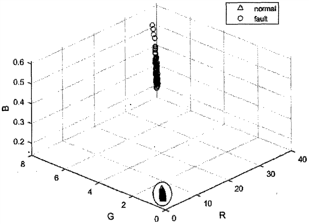
[0044] In this case, select the test data set under normal conditions without load, calculate the RGB-like value, and calculate the hypersphere in the normal state to obtain the center and radius. Then select the test data set of the drive end fault, calculate the RGB-like value, and the distance from the center of the hypersphere in...

Embodiment approach 2

[0066] The data set of the bearing test platform of Case Western Reserve University is used, including normal state Normal, inner ring fault Faultln, rolling ball fault FaultBall, outer ring fault FaultOut, 4 kinds of state data.

[0067] Steps 1 to 3 are the same as steps 1 to 3 in Embodiment 1, and the RGB-like values ​​of the four states are calculated.

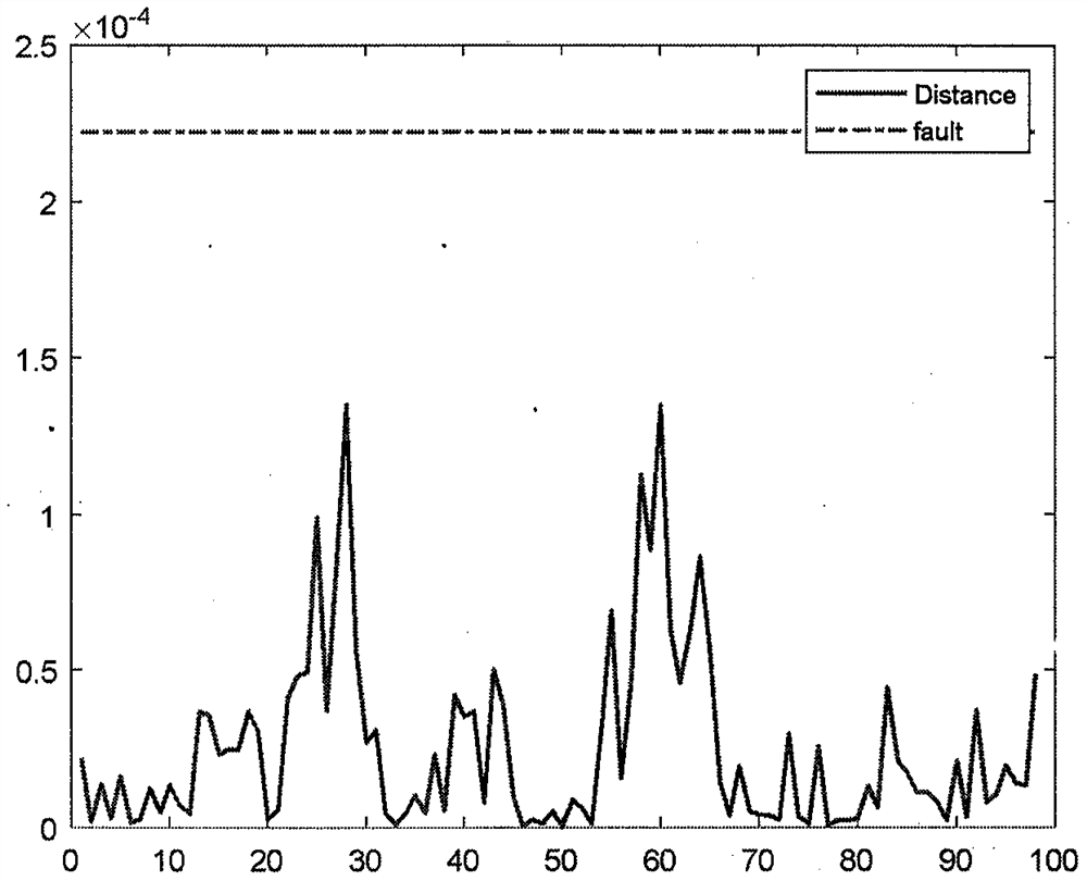
[0068] Step 4), for the 4 state data sets, use the support vector data description method to calculate the hypersphere, and get 4 sphere centers and radii. Among them, c1=[3.3931, 0.812, 0.1518] of hypersphere center in normal state, and λ=2, that is, the fault detection threshold is 0.0002223. Inner circle fault state hypersphere center c1=[31.3754, 6.4175, 0.4353], take λ=1, that is, the threshold value is 0.0261. In the fault state of the rolling ball, the hypersphere center c1=[7.0926, 1.2328, 0.1373], and λ=1, that is, the threshold value is 0.0003906. Outer ring fault state hypersphere center c1=[38.6083, 7.7409, 0...


PUM


Abstract

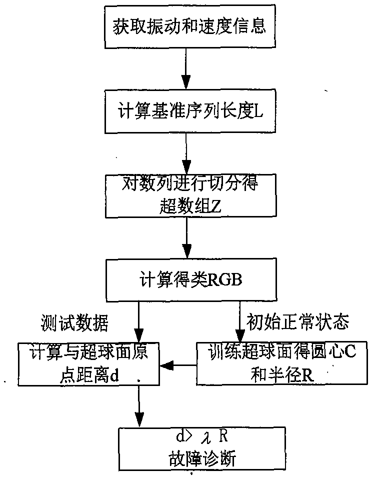
The invention relates to a rolling bearing fault detection method based on a chromaticity theory. The method comprises the steps: employing a chromaticity algorithm to calculate the RGB-like featuresof a bearing according to the collected bearing vibration information, employing a support vector data description algorithm SVDD for classification, and achieving the fault detection. The invention belongs to the technical field of bearing detection. According to the fault detection method, vibration signals which are easy to obtain of the bearing are analyzed, vibration sequence data are converted into frequency domain data through fast Fourier transform, the frequency domain data are converted into RGB-like data through three overlapped digital filters, SVDD serves as a classifier to classify the RGB-like data, and the normal state and the fault state which are represented respectively are obtained. The method provides a basis for fault detection of the bearing.

Description

technical field [0001] The invention relates to a rolling bearing fault state analysis device and method based on chromaticity theory, and belongs to the technical field of fault diagnosis of electromechanical systems. Background technique [0002] As a common support and rotation isolation device in electromechanical systems, ball bearings have been widely used in various AC and DC motor transmission and mechanical rotation occasions. With the improvement of production requirements, electromechanical systems are developing in the direction of high power and high speed, and more and more applications are used in harsh working conditions such as humidity, high temperature, and strong impact, which leads to aggravated aging and wear of bearings. The resulting downtime losses and even the risk of accidents are also increasing. Therefore, real-time fault detection for rolling bearings has important economic and social value. [0003] Traditional bearing fault detection mainly ...

Claims


Application Information

Patent Timeline
Patent Type & Authority Applications(China)
IPC IPC(8): G01M13/045G01D21/02
CPCG01D21/02G01M13/045
Inventor 刘剑慰姜斌杨蒲
Owner NANJING UNIV OF AERONAUTICS & ASTRONAUTICS
Learn More