
Separating device for interrupting a direct current of a current path, and on-board electrical system of a motor vehicle

A technology for separating equipment and current paths, applied in the direction of circuits or fluid pipelines, circuits, circuit devices, etc., can solve the problems of semiconductor switching power loss, inability to ensure electrical separation, and inability to ensure personnel protection, etc., to achieve low pass-through loss paths loss, space saving, ensure the effect of electrical interruption

Pending Publication Date: 2020-11-20
ELLENBERGER POENSGEN
View PDF2 Cites 0 Cited by
  • Summary
  • Abstract
  • Description
  • Claims
  • Application Information

AI Technical Summary

Problems solved by technology

In contrast, if high-power semiconductor switches are used for load separation, power loss in the semiconductor switches is unavoidable even in normal operation
Furthermore, the use of power semiconductors of this type typically may not ensure galvanic separation and thus reliable protection of persons

Method used


Image

  • Separating device for interrupting a direct current of a current path, and on-board electrical system of a motor vehicle

Examples


Embodiment Construction

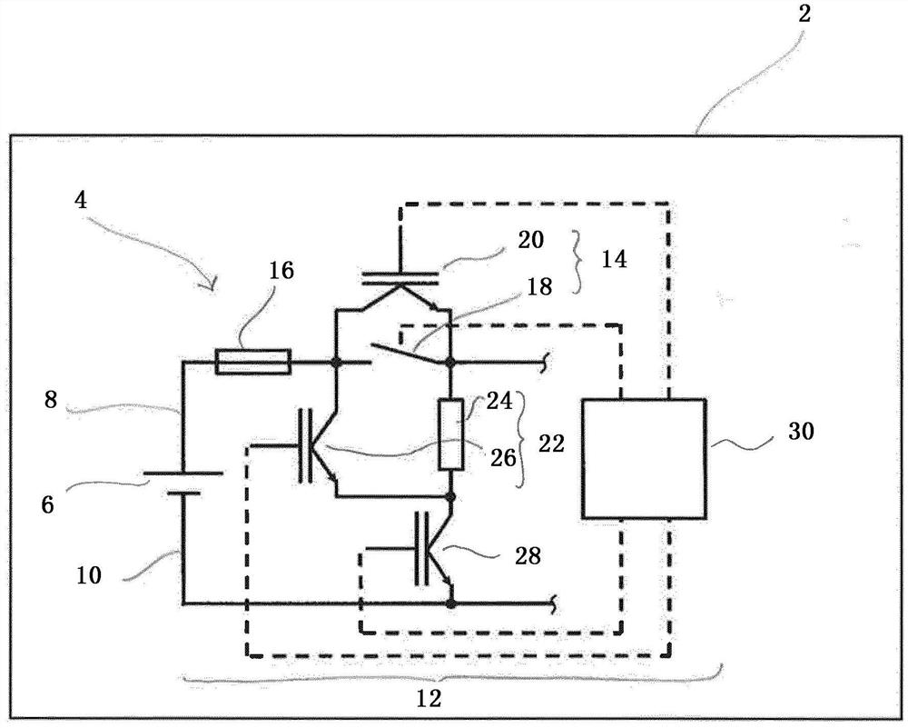
[0025] The drawing shows a motor vehicle 2 in a schematic and simplified illustration. The motor vehicle 2 has an on-board electrical system 4 shown in section. Vehicle electrical system 4 is implemented with an electrochemical battery system 6 as an energy storage or direct current source. A current path 8 , 10 is respectively connected to the poles of the battery system 6 . The current path 8 leading to the positive pole of the battery system 6 is also referred to below as the positive path, and the current path 10 leading to the negative pole of the battery system 6 is also referred to below as the negative path.

[0026] In the exemplary embodiment shown, a disconnecting device 12 is connected in succession in the positive path 8 in order to interrupt the direct current. The disconnecting device 12 has a hybrid switch 14 and an overcurrent protection device 16 upstream of the hybrid switch. In this case, the overcurrent protection device 16 is embodied, for example, as ...


PUM


Abstract

The invention relates to a separating device (12) for interrupting a direct current of a current path (8), in particular for an on-board electrical system (4) of a motor vehicle (2), having a hybrid switch (14) with a current-conducting mechanical contact system (18) and a first semiconductor switch (20) connected to the hybrid switch in parallel and having a switchable resistance cascade (22) with at least one ohmic resistor (24) which is connected to the contact system (18) of the hybrid switch (14) in parallel.

Description

technical field [0001] The invention relates to a disconnecting device for direct current interruption of a current path, in particular for an on-board electrical system of a motor vehicle. The invention also relates to an on-board electrical system for a motor vehicle having such a disconnection device. Background technique [0002] The on-board electrical system is used to supply electrical consumers and utilities with the operating voltage of the on-board electrical system. Such a vehicle electrical system is usually supplied by means of an energy store, for example in the form of an electrochemical battery system. Subject to system constraints, this type of battery system permanently supplies operating current and operating voltage on the one hand, which are set in the low voltage range (NV) of 12V to 48V (DC) and in the range of approximately up to 1500V (DC) or even higher high voltage range (HV). Reliable separation of electrical components or devices from the batt...

Claims


Application Information

Patent Timeline
IPC IPC(8): H01H9/54H01H33/59
CPCH01H9/541H01H33/596B60R16/03G02B1/115G02B5/003G02B5/22H02H3/025B60R16/02B60R16/005H01H9/542H01H2009/544H01H2009/546
Inventor 迪尔克·博舍恩斯特-迪特尔·威尔克宁
Owner ELLENBERGER POENSGEN
Learn More