Alignment device and method for optical axis of collimator and optical axis of optical-mechanical system in stray light testing

A technology of collimator and alignment device, which is applied in the direction of measuring device, optical instrument test, and test of optical performance. The effect of small size and simple operation steps

Active Publication Date: 2020-11-24
XI'AN INST OF OPTICS & FINE MECHANICS - CHINESE ACAD OF SCI
View PDF16 Cites 6 Cited by
  • Summary
  • Abstract
  • Description
  • Claims
  • Application Information

AI Technical Summary

Problems solved by technology

[0007] The purpose of the present invention is to solve the problems of the existing stray light test collimator optical axis and the optical axis alignment of the optical machine system. The operation is difficult, and the focus judgment method of the system to be tested can only be qualitatively judged and is only applicable to the technical problems of a simple optical system. A device and method for aligning the optical axis of the parallel light tube and the optical axis of the optical machine system in the stray light test is provided.

Method used


Image

  • Alignment device and method for optical axis of collimator and optical axis of optical-mechanical system in stray light testing
  • Alignment device and method for optical axis of collimator and optical axis of optical-mechanical system in stray light testing
  • Alignment device and method for optical axis of collimator and optical axis of optical-mechanical system in stray light testing

Examples


Embodiment Construction

[0055] The present invention will be further described below in conjunction with accompanying drawing.

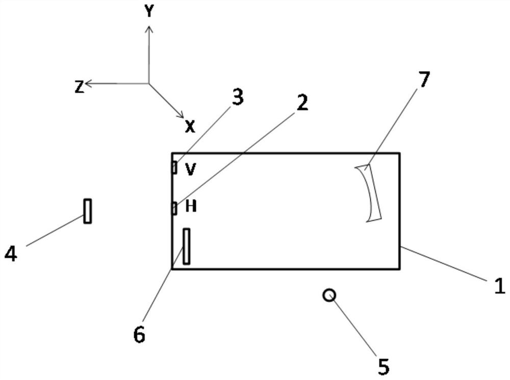
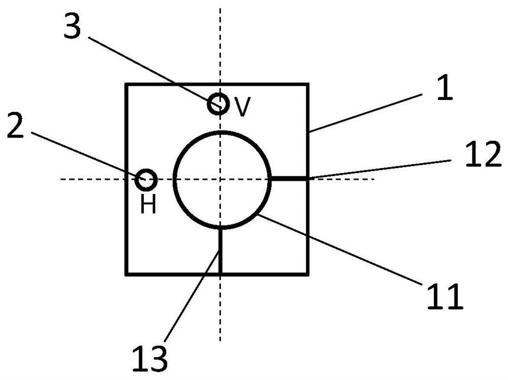
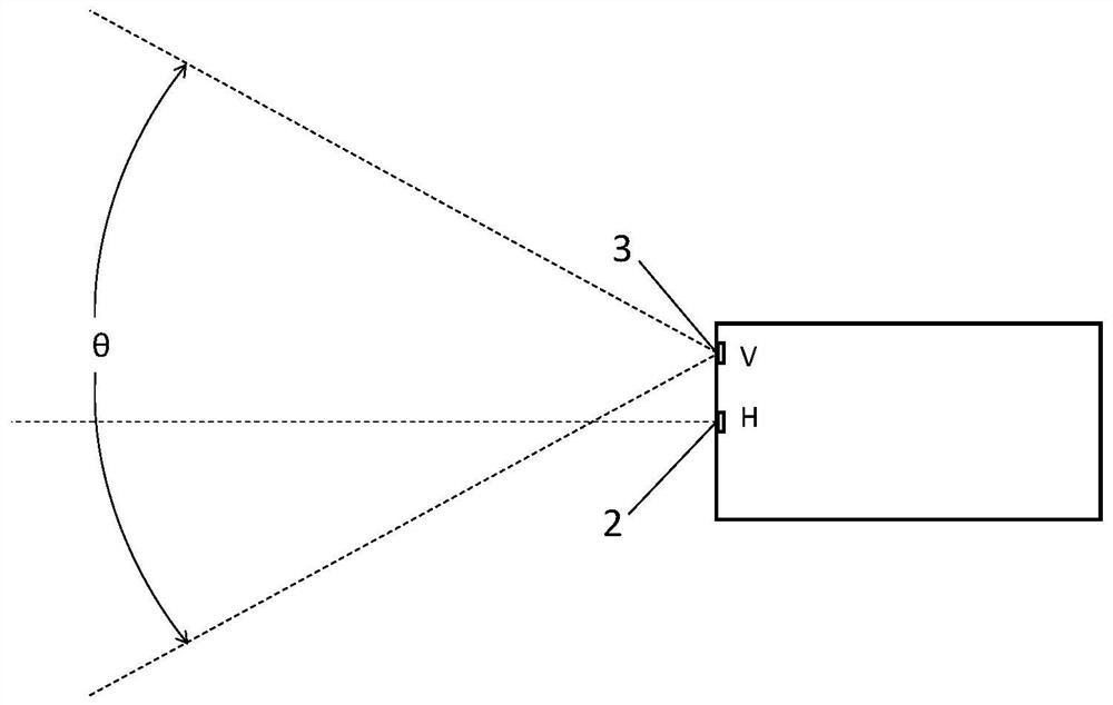
[0056] In the stray light test provided by the present invention, the optical axis of the collimator and the optical axis of the optical mechanical system are aligned, such as Figures 1 to 6 As shown, it includes structural frame 1, horizontal line laser (indicated by H in the figure, the outgoing horizontal laser line is consistent with the X direction) 2, vertical line laser (indicated by V in the figure, the outgoing vertical laser line is consistent with the Y direction) 3 , a receiving screen 4, and an interferometer 5, a plane folding mirror 6 and a parabolic mirror 7 arranged in sequence along the optical path; the plane folding mirror 6 and the parabolic mirror 7 form a collimator; the collimator is arranged on a structural frame 1; the interferometer 5 is arranged at the focal point of the collimator; the exit end face of the structural frame 1 is provided with an e...


PUM


Abstract

The invention relates to an alignment device and method, in particular to an alignment device and method for the optical axis of a collimator and the optical axis of an optical-mechanical system in stray light testing. The invention aims to solve the problems in the prior art, an auto-collimation aiming method has the technical problems that the device structure is complex, the cost is high, the cubic mirror indirect optical axis leading-out method is low in efficiency and high in operation difficulty, and a to-be-tested system focusing judgment method can only carry out qualitative judgment and is only suitable for a pure optical system. The alignment device and method for the optical axis of a collimator and the optical axis of an optical-mechanical system in stray light testing are provided. A collimator is formed by a planar folding shaft mirror and a parabolic mirror of the device and is arranged in a structural frame. The horizontal line laser and the vertical line laser are bothinstalled on the structural frame and emit laser rays which are reflected by an X-axis reference plane mirror and a Y-axis reference plane mirror of the to-be-measured optical machine system respectively, and the permeable receiving screen is arranged in a common area of the horizontal laser rays, the vertical laser rays and respective reflected laser rays. The method is carried out by using thedevice.

Description

technical field [0001] The invention relates to an alignment device and method, in particular to a device and method for aligning the optical axis of a parallel light tube and the optical axis of an optical machine system in a stray light test. Background technique [0002] Collimator is the most basic optical instrument in optical calibration and inspection. Collimator and light source can provide infinite collimation target, which is used to simulate space target with different characteristics, such as in stray light test (that is, point source transmission In the stray light test, referred to as the stray light test), since the transmittance curve of the point source is the angular distribution function of the stray light of the optomechanical system to be tested, it is necessary to align the collimator with the optical axis of the light source to match the simulated infinity Stray light (stray light) is radiated, and then the optical axis of the collimator is calibrated ...

Claims


Application Information

Patent Timeline
Patent Type & Authority Applications(China)
IPC IPC(8): G01M11/02G02B27/62G02B7/00
CPCG01M11/0207G02B7/003G02B27/62
Inventor 陈钦芳薛要克马占鹏沈阳林上民刘美莹
Owner XI'AN INST OF OPTICS & FINE MECHANICS - CHINESE ACAD OF SCI
Why Eureka
Try Eureka