Motor current detection method and system, stirrer and storage medium
A technology of motor current and detection method, which is applied in the direction of measuring current/voltage, measuring device, measuring electric variable, etc., can solve the problem of high cost of current detection, and achieve the effect of saving detection cost and saving the space of the overall structure
- Summary
- Abstract
- Description
- Claims
- Application Information
AI Technical Summary
Problems solved by technology
Method used
Image

Examples
Embodiment 1
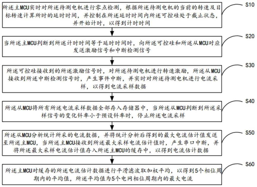
[0054] see figure 1 , is a flow chart of the motor current detection method provided in the first embodiment of the present invention. In this embodiment, the motor to be tested is electrically connected to a master MCU and a slave MCU respectively, and the slave MCU is connected to the motor to be tested. Provided with a thyristor, the method comprises the steps of:
[0055]Step S10, the main MCU detects the zero point of the motor under test in real time, calculates the delay time according to the current speed and the target speed of the motor under test, and controls the time delay within the delay time. The thyristor is in the cut-off state and starts timing to obtain the timing time;
[0056] Specifically, the main MCU detects the zero-crossing point in each phase of the motor in real time through the zero-crossing detection circuit, and when it is judged that the current zero-crossing point of the motor under test is detected, the timer is triggered to achieve the timi...
Embodiment 2
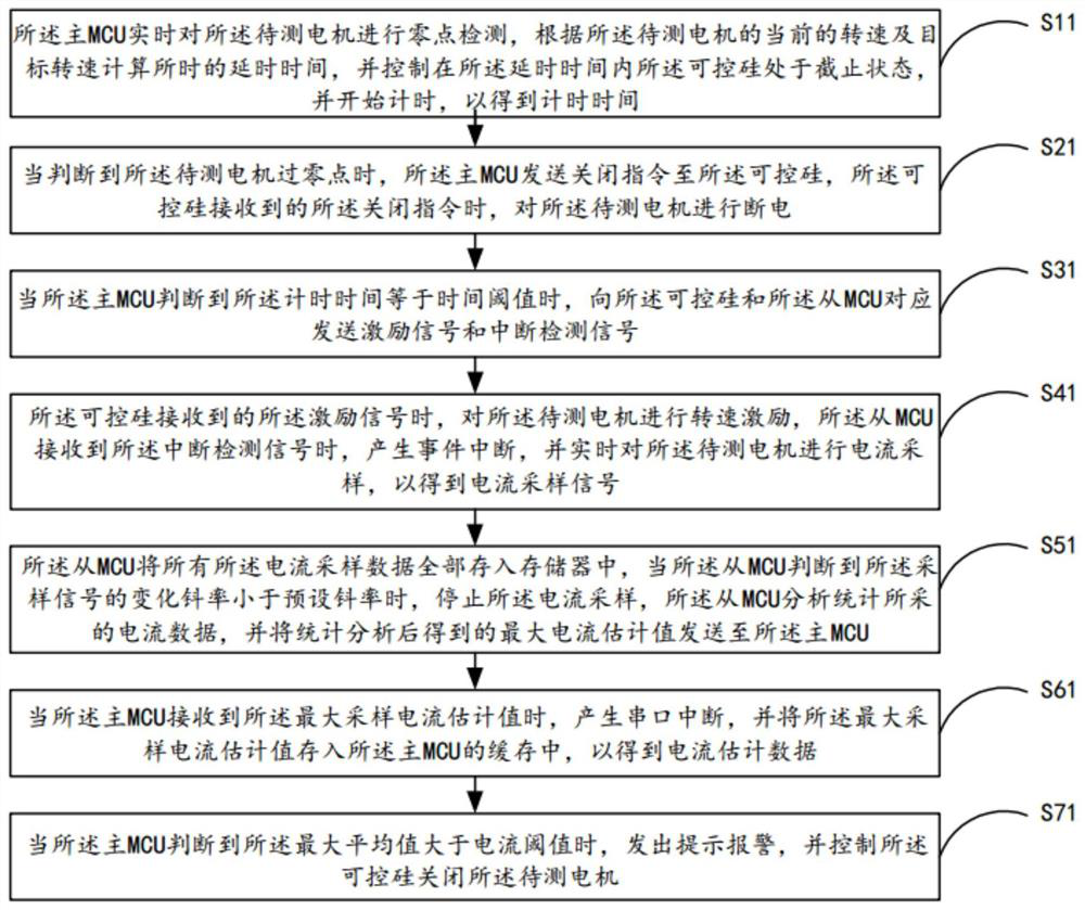
[0069] see figure 2 , is a flow chart of the motor current detection method provided in the first embodiment of the present invention. In this embodiment, the motor to be tested is electrically connected to a master MCU and a slave MCU respectively, and the slave MCU is connected to the motor to be tested. Provided with a thyristor, the method comprises the steps of:
[0070] Step S11, the main MCU detects the zero point of the motor under test in real time, calculates the delay time according to the current speed and target speed of the motor under test, and controls the time delay within the delay time. The thyristor is in the cut-off state and starts timing to obtain the timing time;
[0071] Step S21, when it is judged that the motor under test is at a zero point, the main MCU sends a shutdown command to the thyristor, and when the thyristor receives the shutdown command, the motor under test is power off;
[0072] Wherein, the shutdown command is used to control and s...
Embodiment 3
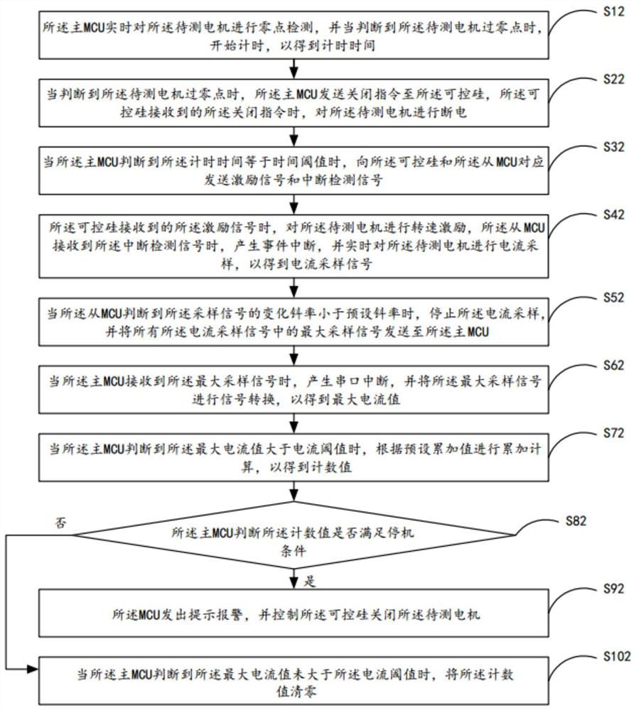
[0082] see image 3 , is a flow chart of the motor current detection method provided by the third embodiment of the present invention. In this embodiment, the motor to be tested is electrically connected to a master MCU and a slave MCU respectively, and the slave MCU and the motor to be tested are connected electrically. Provided with a thyristor, the method comprises the steps of:
[0083] Step S12, the main MCU detects the zero point of the motor under test in real time, and starts timing when it is judged that the motor under test crosses the zero point, so as to obtain the timing time;
[0084] Step S22, when it is judged that the motor under test has crossed zero, the main MCU sends a shutdown command to the thyristor, and when the thyristor receives the shutdown command, the motor under test is power off;
[0085] Step S32, when the master MCU judges that the counting time is equal to a time threshold, correspondingly send an excitation signal and an interrupt detectio...
PUM
 Abstract
Description
Claims
Application Information
 - Generate Ideas
- Intellectual Property
- Life Sciences
- Materials
- Tech Scout
- Unparalleled Data Quality
- Higher Quality Content
- 60% Fewer Hallucinations
Browse by: Latest US Patents, China's latest patents, Technical Efficacy Thesaurus, Application Domain, Technology Topic, Popular Technical Reports.
© 2025 PatSnap. All rights reserved.Legal|Privacy policy|Modern Slavery Act Transparency Statement|Sitemap|About US| Contact US: help@patsnap.com