
Electrostatic micro-lubricating based cutting device

A micro-lubrication and charging device technology, applied in grinding/polishing equipment, grinding machines, metal processing equipment, etc., can solve the problems of threatening the health of operators, splashing a lot of mist and water, and harming the health of workers, etc. Satisfy the benefits of green environmental protection, improve lubrication and heat transfer capacity, and improve the effect of processing quality

Pending Publication Date: 2020-11-27
ZHEJIANG UNIV OF TECH
View PDF0 Cites 3 Cited by
  • Summary
  • Abstract
  • Description
  • Claims
  • Application Information

AI Technical Summary

Problems solved by technology

This also brings a lot of trouble and damage: the high temperature generated during the machining process makes the cutting fluid gradually evolve into mist and volatilize. During the evaporation process, many mist particles and water splashes will be splashed. Once inhaled by the operator, it will directly Threatening the health of the operator and polluting the surrounding environment virtually; some cutting fluids have special properties, and the chips attached to them are usually treated as harmful substances. additives, its cutting fluid is difficult to degrade through natural means, so it often leads to environmental pollution
At the same time, the additives used in the cutting fluid will also bring great harm to the health of the staff, and at the same time affect the processing quality

Method used


Image

  • Electrostatic micro-lubricating based cutting device
  • Electrostatic micro-lubricating based cutting device
  • Electrostatic micro-lubricating based cutting device

Examples


Embodiment Construction

[0024] The present invention will be further described below in conjunction with the accompanying drawings of the description.

[0025] The purpose of the present invention is to explore the characteristics of existing hydraulic devices and the principle characteristics of plunger pumps and their applications, the application of pneumatic frequency generators and electrostatic generators, and proposes a device based on electrostatic micro-lubrication cutting, using Pneumatic plunger pump cooperates with pulse and frequency to control the entry of gas, and directly merges and charges through the confluence device in the box. This internal device has better applicability and higher durability in the actual factory processing environment, which is beneficial to ensure the required processing efficiency. During the electrostatic micro-lubrication grinding process, the electrostatic field accelerates the diffusion of carbon atoms and the dissolution of cementite, increases the rela...


PUM


Abstract

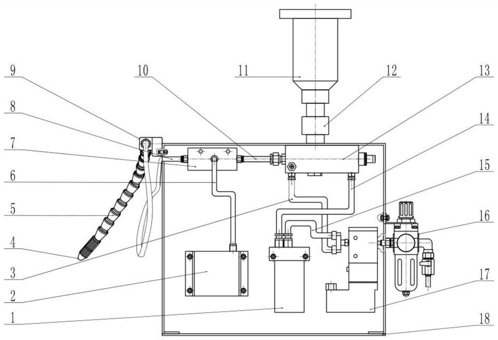
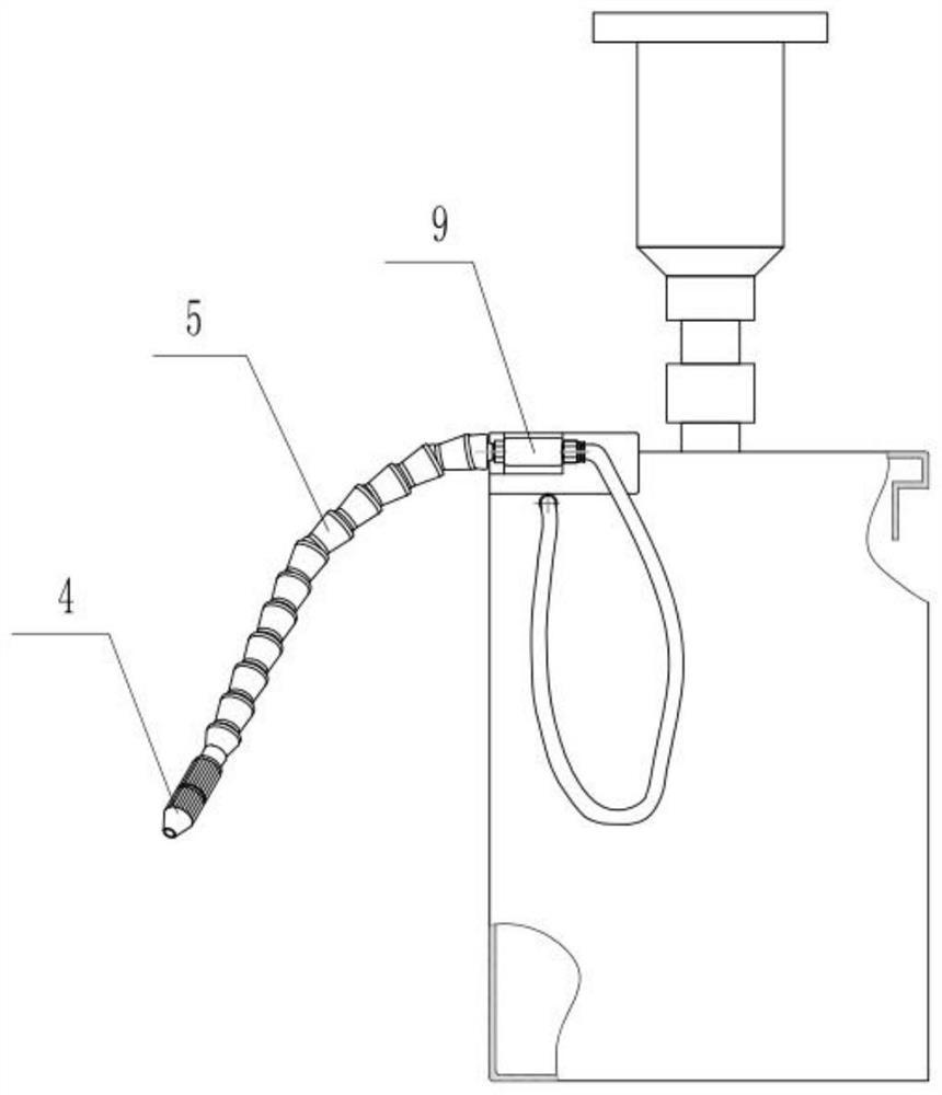
The invention discloses an electrostatic micro-lubricating based cutting device. The device comprises a box body, wherein a liquid storage device used for storing cutting fluid is arranged at the topof the box body, an air source adjusting processor is arranged on the side surface of the box body, a pneumatic plunger pump, an electromagnetic valve, an electrostatic generator, a gas-liquid electric converging device and a pneumatic frequency generator are arranged in the box body, the air source adjusting processor is connected with the electromagnetic valve in the box body, a first air pipe and a third air pipe are arranged on the electromagnetic valve, the electromagnetic valve is connected with the pneumatic plunger pump through the first air pipe, the electromagnetic valve is connectedwith the pneumatic frequency generator through the third air pipe, and the pneumatic frequency generator is connected with the pneumatic plunger pump through a second air pipe. The electrostatic micro-lubricating based cutting device has the beneficial effects that the charged lubricating fluid under the condition of electrostatic micro-lubrication has better lubricating and cooling capacity, sothat the processing quality of a workpiece is improved, the use of the lubricating fluid is reduced, and the environment-friendly benefit can be further met.

Description

technical field [0001] The invention relates to the technical field of micro-lubrication cutting, in particular to a cutting device based on electrostatic micro-lubrication. Background technique [0002] Minimal quantity lubrication refers to lubrication conditions in which very small amounts of lubricant are used. It is used in cutting, high-speed rotating machinery such as high-speed centrifuge using this lubrication method. It is also called minimum quantity lubrication in mechanical cutting, that is, the minimum amount of cutting fluid is used to achieve the best cutting effect. It is a kind of lubrication method for metal processing, that is, semi-dry cutting. Usually, compressed air (air, nitrogen, carbon dioxide, etc.) is mixed and vaporized with a very small amount of lubricating oil to form a micron-sized droplet oil mist, which is then sprayed into the cutting area or the moving pair through the nozzle at high speed, so that the cutting area or the moving pair Ef...

Claims


Application Information

Patent Timeline
Patent Type & Authority Applications(China)
IPC IPC(8): B24B57/02B24B27/06
CPCB24B27/06B24B57/02
Inventor 黄斌刘建飞陈肖王柳闵邱绵振于燕坤蔡姚杰
Owner ZHEJIANG UNIV OF TECH
Learn More