Vacuum grouting device for microbial seepage prevention of jointed rock mass and using method thereof

A grouting device and a technology for cracked rock mass, applied in soil protection, construction, infrastructure engineering, etc., can solve the problems of grout diffusion distance in new cracks, unstable and insufficient grouting pressure, etc.

Active Publication Date: 2020-11-27
SOUTHWEST PETROLEUM UNIV
View PDF4 Cites 3 Cited by
  • Summary
  • Abstract
  • Description
  • Claims
  • Application Information

AI Technical Summary

Problems solved by technology

[0004] The purpose of the present invention is to provide a vacuum grouting device and method of use for microbiological anti-seepage of cracked rock mass, which solves the defects of the existing microbial

Method used


Image

  • Vacuum grouting device for microbial seepage prevention of jointed rock mass and using method thereof
  • Vacuum grouting device for microbial seepage prevention of jointed rock mass and using method thereof

Examples


Embodiment 1

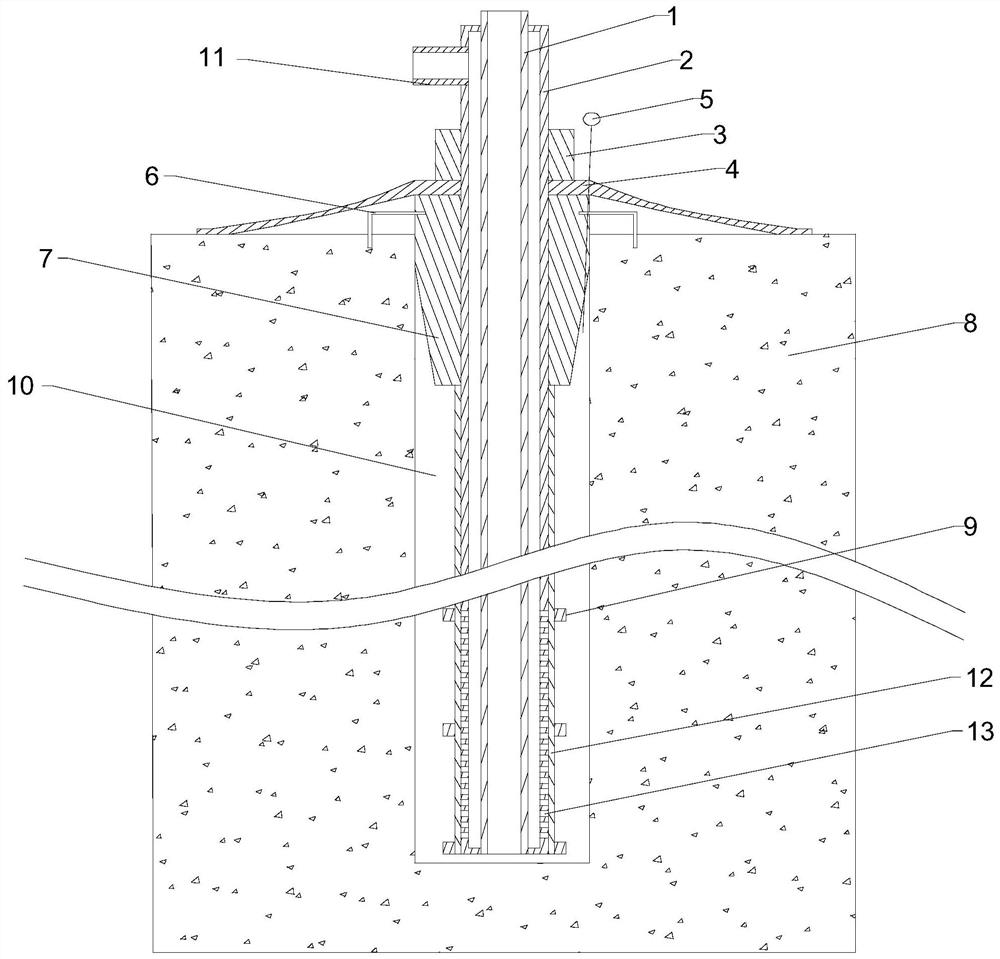
[0040] like Figure 1~2 As shown, this embodiment includes a suction pipe 2 with both ends closed, and a plurality of suction holes 13 are opened on the outer peripheral wall of the lower section along the circumferential direction of the suction pipe 2. Inside the suction pipe 2 A grouting pipe 1 is provided, both ends of the grouting pipe 1 run through both ends of the suction pipe 2, and the upper end of the grouting pipe 1 extends upwards, and the lower end surface of the grouting pipe 1 is flush with the lower end surface of the suction pipe 2 Flat, along the axis of the suction pipe 2, a nut 3, a spacer 4 and a grout stopper 7 are sequentially sleeved on the outer peripheral wall of the upper section from top to bottom. The non-woven fabric 12 covering the suction hole 13 is provided with an exhaust pipe 11 communicating with the inside of the suction pipe 2 on the side wall of the upper section, and the outer diameter of the stopper 7 is the same as the inner diameter o...

Embodiment 2

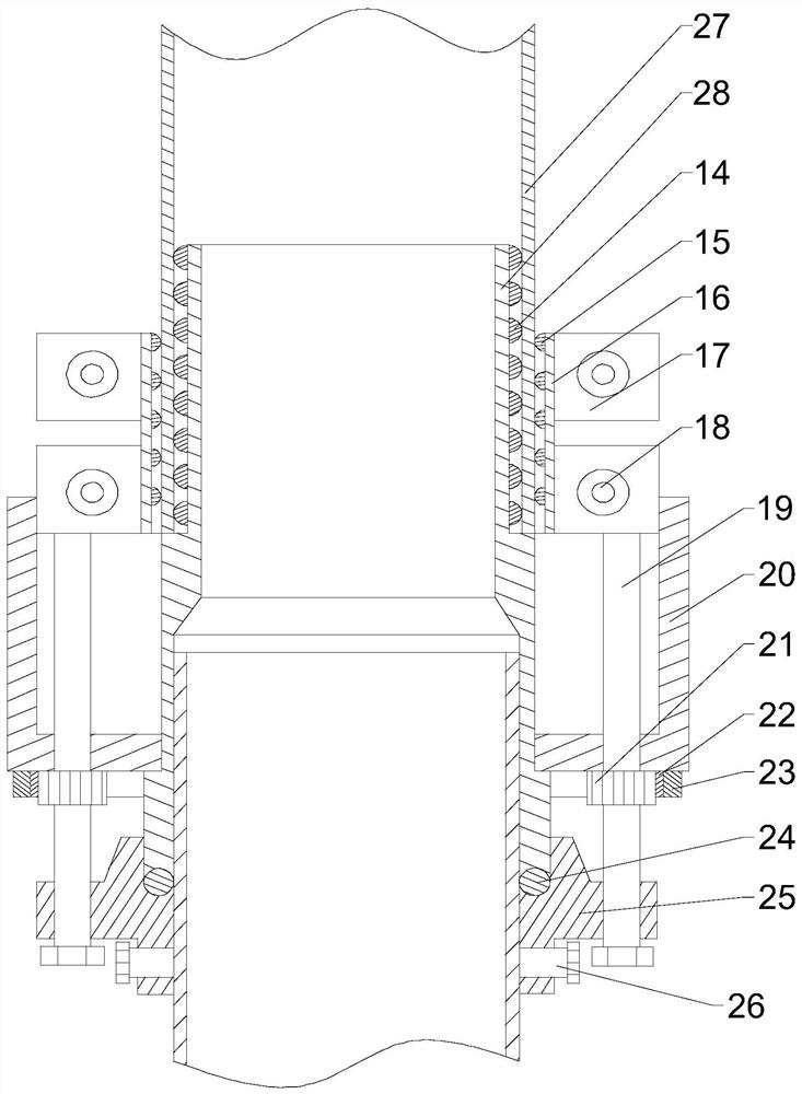
[0046] like figure 2As shown, the connecting assembly described in this embodiment includes a connecting pipe 28, a sleeve 20 is fixed in the middle of the outer peripheral wall of the connecting pipe 28, and an annular recess is formed on the inner peripheral wall of the sleeve 20 along the circumferential direction. groove, and one end of the annular groove is open, a clamp 16 is sleeved on the outer wall of one end of the connecting pipe 28, and the clamp 16 is slidably arranged in the annular groove, and a stopper is provided on the outer wall of the other end of the connecting pipe 28. The back ring 25 has two limit screw holes on the back ring 25 along the axial direction of the connecting pipe 28, and two positioning screw holes on the back ring 25 along the radial direction of the connecting pipe 28. The screw rod 19 After cooperating with the limit screw thread, the activity runs through the closed end of the annular groove and is ball-connected with the clamp 16. Th...

Embodiment 3

[0052] like Figure 1~2 As shown, this embodiment includes the following steps:

[0053] S 1 1. Three grouting holes 10 are drilled, the three grouting devices respectively seal the three grouting holes 10, and the three grouting devices are successively defined as grouting device I, grouting device II, and grouting device III, The three grouting holes 10 are sequentially defined as grouting hole I, grouting hole II, and grouting hole III;

[0054] S 2 . Connect the grouting pipe 1 of the grouting device I and the grouting device III with the cementing solution tank, and connect the grouting pipe 1 of the grouting device II with the bacteria solution tank;

[0055] S 3 1. Turn on the vacuum pump connected to the grouting device I and the grouting device III, draw a vacuum from the grouting hole I and the grouting hole III, and at the same time inject the bacterial solution into the grouting hole II from the grouting device II;

[0056] S 4 . When the water and air separa...


PUM


Abstract

The invention discloses a vacuum grouting device for microbial seepage prevention of a jointed rock mass and a using method thereof. A plurality of suction holes are formed in an outer wall of a lowersection of a suction pipe, a grouting pipe is arranged in the suction pipe, an upper end of the suction pipe extends upwards, a nut, a spacer and a stop-grouting plug are sleeved on the outer wall ofthe upper section of the suction pipe, a non-woven fabric is arranged on the outer wall of the lower section of the suction pipe, and an exhaust pipe is arranged on the side wall of the upper sectionof the suction pipe; three grouting holes are drilled when a rock mass is subjected to grouting anti-seepage; and after grouting devices are placed in the grouting holes, the three grouting devices alternately perform grouting. The vacuum grouting device adopts vacuum negative pressure grouting. For the jointed rock mass, good effects are hard to be achieved by using common intravenous grouting and other traditional methods. With the aid of vacuum negative pressure, the original air and water in the rock mass that hinder the advancement of the grout are removed; at the same time, the tiny airbubbles in fissures are sucked and discharged together, so that the effective contact between a bacterial liquid the rock particles is more, so as to improve anti-seepage effect.

Description

technical field [0001] The invention relates to the technical field of solidification and anti-seepage in rock mass engineering, and specifically provides a microbial solidification and anti-seepage device that can be applied to target cracks in rock mass and adopts a vacuum grouting process. Background technique [0002] The problem of solidification and anti-seepage of rock mass has always been an inevitable topic in construction engineering, and it is also a key research direction for scholars in the field of rock mass engineering. At present, the solution to the problem of solidification and anti-seepage of rock mass is mostly to block the target cracks through high-pressure grouting technology, so as to repair the weakness and leakage of rock mass. According to the different grouting materials, it can usually be subdivided into cement grouting, chemical grouting, and mixed grouting grouting. Cement grouting technology can inject solidified cement slurry into the rock b...

Claims


Application Information

Patent Timeline
IPC IPC(8): E02D3/12
CPCE02D3/12
Inventor 郭亮廖明伟彭颐祈王银帅戴启辰刘丰威李佳艺郭豪何肖玉阿布拉铁张军伟
Owner SOUTHWEST PETROLEUM UNIV
Why Eureka
Try Eureka