Endoscopic heat pipe visualization device and test method

An endoscopic heat pipe technology, applied in the "endoscopic" heat pipe visualization device and testing field, can solve the problem of visualization of the working fluid two-phase flow mechanism inside the metal wall heat pipe, which has not been reported and cannot truly reflect the phase change of the working fluid Behavior and mechanisms of two-phase heat transfer

Active Publication Date: 2020-11-27
NANJING UNIV OF TECH
View PDF9 Cites 3 Cited by
  • Summary
  • Abstract
  • Description
  • Claims
  • Application Information

AI Technical Summary

Problems solved by technology

Although the glass visualization experiment can clearly observe the two-phase flow state inside the heat pipe, the heat pipe with a glass wall cannot truly reflect the phase transition behavior of the working fluid on the m

Method used


Image

  • Endoscopic heat pipe visualization device and test method
  • Endoscopic heat pipe visualization device and test method
  • Endoscopic heat pipe visualization device and test method

Examples


Embodiment 1

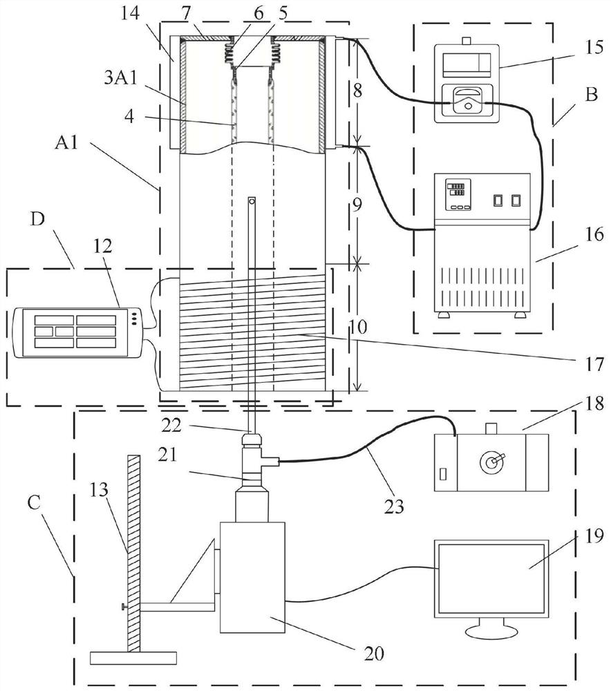
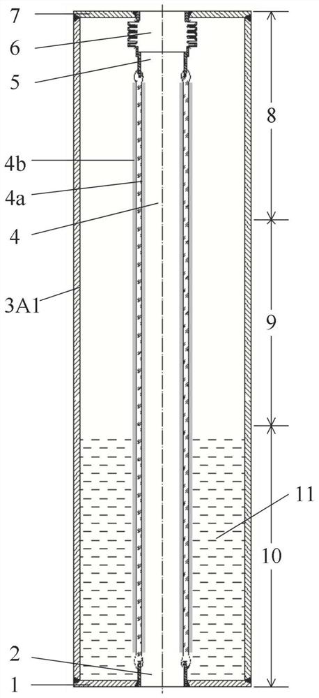
[0030] figure 1 Shown is the test system diagram of the "endoscopic" gravity heat pipe visualization device of this example, and the structural schematic diagram of the "endoscopic" gravity heat pipe of this example is shown in figure 2 shown.

[0031] The "endoscopic" gravity heat pipe visualization experiment device consists of an "endoscopic" gravity heat pipe A1, a cooling system B, a shooting system C and a heating system D; the "endoscopic" gravity heat pipe A1 consists of a gravity heat pipe main pipe 3A1 , a transparent glass tube 4, a first Kovar ring 2, a second Kovar ring 5, an expansion joint 6, a first end cap 1 and a second end cap 7, and a working fluid 11; wherein the heat pipe main body tube 3A1 is composed of The evaporation section 10, the heat insulation section 9 and the condensation section 8 are composed; the main tube 3A1 of the gravity heat pipe is placed vertically, the transparent glass tube 4 is coaxially placed inside the main tube 3A1 of the gra...

Embodiment 2

[0036] Figure 4 Shown is the structural schematic diagram of the "endoscopic" gravity heat pipe of this example. The structural form, some materials and the testing process of this embodiment are basically the same as those of Embodiment 1. The difference is: the main tube 3A1 of the "endoscopic" gravity heat pipe is a combined tube, the material is aluminum, and the characteristic shape of the condensation section 8 is a bellows, the total length is 450m, the diameter of the straight section of the bellows is 80mm, and the peak diameter of the bellows is 100mm. The length of the straight section is 20mm, the length of the arc section is 30mm, and the thickness is 3mm; the characteristic shape of the heat insulation section 9 is a straight pipe, the length is 100mm, the diameter is 80mm, and the thickness is 3mm; the characteristic shape of the evaporation section 10 is a straight pipe, the length is 400mm, the diameter is 80mm, and the wall The thickness is 3mm, the inner w...

Embodiment 3

[0039] Figure 5 Shown is the test system diagram of the "endoscopic" loop heat pipe visualization device of this example, and the structural schematic diagram of the "endoscopic" loop heat pipe of this example is shown in Image 6 As shown; the visualization device of this example is basically the same as that of Example 1, the difference is that the "endoscopic" loop heat pipe A2 consists of a loop heat pipe main body tube 3A2, a transparent glass tube 4, a first Kovar ring 2 and Second Kovar ring 5, expansion joint 6, first end cap 1 and second end cap 7, U-shaped liquid storage pipe 9c, steam ascending pipe 9b, condensate descending pipe 9a, condensation section 8, liquid-absorbing core 10a and the heat pipe working fluid 11; the loop heat pipe main tube 3A2 is placed horizontally, the transparent glass tube 4 is placed inside the loop heat pipe main tube 3A2, and the two ends are respectively connected with the first Kovar alloy ring 2 and the second Kovar alloy ring 5 S...


PUM

PropertyMeasurementUnit
Diameteraaaaaaaaaa
Lengthaaaaaaaaaa
Wall thicknessaaaaaaaaaa

Abstract

The invention relates to an endoscopic heat pipe visualization device and a test method. The endoscopic heat pipe visualization device comprises an endoscopic heat pipe (A1 or A2), a cooling system (B), a shooting system (C) and a heating system (D), wherein the endoscopic heat pipe (A1 or A2) consists of a heat pipe main body pipe (3A1 or 3A2), a transparent glass pipe (4) and a working medium (11), and is sealed through a first kovar alloy ring (2), a second kovar alloy ring (5), an expansion joint (6), a first end cover (1) and a second end cover (7); the transparent glass pipe (4) is placed in the heat pipe main body pipe (3A1 or 3A 2); and an endoscope (22) is connected with a high-speed camera (20), and extends into the transparent glass pipe (4) to shoot the phase change and the two-phase flow pattern of the working medium (11) in the heat pipe main body pipe (3A1 or 3A 2). The device and the method are suitable for disclosing a phase change heat and mass transfer mechanism of the working medium in the heat pipe under a metal wall surface; the test process is closer to actual working conditions; and the reliability of test results is improved.

Description

technical field [0001] The invention relates to an "endoscopic" heat pipe and a visual test method thereof, which is particularly suitable for the visual experimental research on the phase change of working fluid inside the metal heat pipe and the mechanism of two-phase flow. Background technique [0002] Heat pipe is an efficient heat transfer device with simple structure and flexible features. It has been widely used in the fields of aerospace electronic components cooling, EMU cooling, petrochemical industry, solar collectors, and waste heat recovery. The heat pipe is a complex phenomenon of boiling, condensation and two-phase flow in a confined space, and has a complex heat and mass transfer mechanism. The study of its phase change heat transfer and two-phase flow mechanism plays an important role in optimizing the structure of heat pipes and improving heat transfer performance. [0003] In the study of the heat and mass transfer mechanism of heat pipes, techniques such...

Claims


Application Information

Patent Timeline
IPC IPC(8): F28D15/02F28D15/06G01N25/02G02B23/24
CPCF28D15/0266F28D15/06G01N25/02G02B23/24
Inventor 朱跃钊姚慧聪王银峰
Owner NANJING UNIV OF TECH
Why Eureka
Try Eureka