High-power sinusoidal signal generating circuit and method for cross-well electromagnetism

A sinusoidal signal and circuit generation technology, which is applied in the direction of electric/magnetic detection, electric pulse generation, and electromagnetic wave detection for well logging records, to achieve the effects of increasing radiation power, reducing loss, and accurate radiation phase

Pending Publication Date: 2020-11-27
UNIV OF ELECTRONICS SCI & TECH OF CHINA
View PDF3 Cites 2 Cited by
  • Summary
  • Abstract
  • Description
  • Claims
  • Application Information

AI Technical Summary

Problems solved by technology

[0004] The purpose of the present invention is to overcome the shortcomings of the prior art, provide a high-power sinusoidal signal gen

Method used


Image

  • High-power sinusoidal signal generating circuit and method for cross-well electromagnetism
  • High-power sinusoidal signal generating circuit and method for cross-well electromagnetism
  • High-power sinusoidal signal generating circuit and method for cross-well electromagnetism

Examples


Embodiment 1

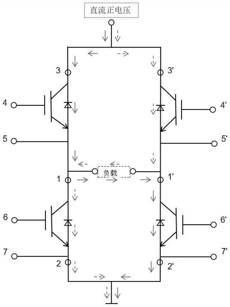
[0027] Such as figure 1 As shown, a high-power sinusoidal signal generation circuit for cross-well electromagnetic, which includes an IGBT switch circuit; the IGBT switch circuit is used to generate twice the same amplitude and opposite polarity, and the SPWM modulated rectangular wave signal is loaded to On the load, it includes a first IGBT module and a second IGBT module, the first IGBT module and the second IGBT module are commonly connected to both ends of the load; the first IGBT module and the second IGBT module each include two stages Connected triodes, four triodes are connected to form a loop.

[0028] Further, it also includes a drive module and a control module; the drive module uses EXB841, the input voltage is 20V, the output positive voltage is 15V, and the negative voltage is 5V as the drive voltage of the IGBT switch circuit; the control module is an FPGA control board, which is used to realize the output SPWM modulation method wave as the control voltage wav...

Embodiment 2

[0034] The present invention also includes a signal generation method for a high-power sinusoidal signal generation circuit for cross-well electromagnetics, the signal generation method comprising:

[0035]After the load antenna is loaded, a DC voltage is applied to both ends of the IGBT switch circuit, and the maximum voltage of the transmission can reach 1200V, and the current is 20A, which greatly increases the transmission power;

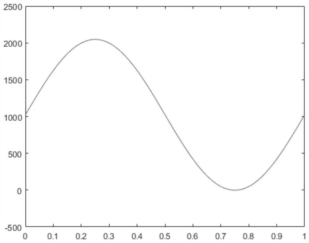
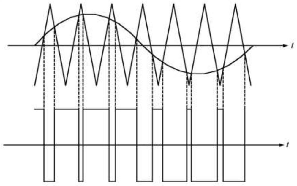
[0036] The FPGA control board outputs 4 control voltages to load the voltage loading points 4, 5, 4', 5', 6, 7, 6', 7' of the IGBT switch circuit, and at the same time, the triangular wave and The sine wave generated by sampling is compared to generate the SPWM signal required by the control voltage, the signal generated by the IGBT switch circuit is SPWM modulated, and finally a rectangular wave signal with the same amplitude and opposite polarity and SPWM modulation is loaded into the On the antenna load, the signal modulated by SPWM becomes a...


PUM


Abstract

The invention relates to a high-power sinusoidal signal generating circuit for cross-well electromagnetism. The high-power sinusoidal signal generating circuit comprises an IGBT switching circuit. TheIGBT switching circuit is used for generating two rectangular wave signals which are identical in amplitude and opposite in polarity and are subjected to SPWM modulation to be loaded to a load, and comprises a first IGBT module and a second IGBT module, and the first IGBT module and the second IGBT module are jointly connected with the two ends of the load. Each of the first IGBT module and the second IGBT module comprises two cascaded triodes, and the four triodes are connected to form an annular loop. The high-power sinusoidal signal generating circuit has the advantages that an IGBT high-power tube is used as the switching tube of a cross-well electromagnetic signal source, so that the radiation power of a cross-well electromagnetic antenna can be effectively increased, and signals ofa cross-well electromagnetic detection system can be radiated farther; the radiation signal waveform is a sine wave, the loss of signal energy caused by antenna impedance due to voltage change can beeffectively reduced, more phase and amplitude information can be contained compared with square waves, and more cross-well geological information is further contained.

Description

technical field [0001] The invention relates to the field of cross-well electromagnetic detection, in particular to a high-power sinusoidal signal generating circuit and method for cross-well electromagnetic. Background technique [0002] Crosswell electromagnetic detection has been developed for many years since it was discovered that it can be applied to ground exploration, but it is still a relatively new technology in the field of ground exploration and well logging; in geological exploration, electromagnetic survey is a commonly used method. The method of ingesting the response of artificial electric field and magnetic field to obtain the information of the conductivity structure of the ore body or geological body under the surface; electromagnetic detection between wells is to use low-frequency electromagnetic waves (generally ranging from 5Hz to 1MHz) in a well, Receive the electromagnetic wave in another or several wells, and calculate the electrical conductivity by ...

Claims


Application Information

Patent Timeline
IPC IPC(8): H03K3/80H03K3/012H03K17/567H03K17/296H03K7/08G01V3/30
CPCH03K3/80H03K3/012H03K17/567H03K17/296H03K7/08G01V3/30
Inventor 赵青张恒赵怿哲郭成严中焦蛟张磊刘巍
Owner UNIV OF ELECTRONICS SCI & TECH OF CHINA
Why Eureka
Try Eureka