Urea hydrolysis ammonia production equipment

A urea hydrolysis and equipment technology, applied in the preparation/separation of ammonia, ammonia compounds, inorganic chemistry, etc., can solve the problems of wasting urea solution and catalyst solution, save catalyst and urea solution, and improve reaction efficiency

Pending Publication Date: 2020-12-01
CHINA HUADIAN ENG +2
View PDF0 Cites 0 Cited by
  • Summary
  • Abstract
  • Description
  • Claims
  • Application Information

AI Technical Summary

Problems solved by technology

[0005] Therefore, the technical problem to be solved in the present invention is to overcome the defects of waste of urea solution and catalyst solution when the reactor is overhauled by the ur

Method used


Image

  • Urea hydrolysis ammonia production equipment

Examples


Embodiment 1

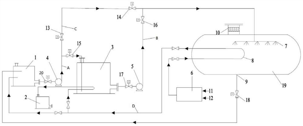
[0027] This embodiment provides a specific implementation of urea hydrolysis ammonia production equipment, such as figure 1 As shown, the urea hydrolysis ammonia production equipment includes a raw material dissolution tank 1 , a raw material storage tank 3 , a reactor 19 , a drain tank 2 and a temperature and pressure reducer 6 .

[0028] The raw material storage tank 3 communicates with the raw material dissolving tank 1 through the first pipeline A, and the first pipeline A is provided with the raw material dissolving pump 4, the first automatic valve 15, and the seventh automatic valve 20; the reactor 19 is connected with the raw material storage tank through the urea pipeline B. The tank 3 is connected, and the urea pipeline B is provided with a raw material delivery pump 5, a second automatic valve 16, and a fourth automatic valve 17; the bottom of the reactor 19 is also communicated with the raw material dissolution tank 1 through a liquid phase pipeline 9, and A third ...


PUM


Abstract

The invention relates to the technical field of chemical material preparation, and especially relates to urea hydrolysis ammonia production equipment. The equipment comprises a raw material dissolvingtank, a raw material storage tank, a reactor, a drain tank and a temperature and pressure reducer, the raw material storage tank is communicated with the raw material dissolving tank through a firstpipeline, and a raw material dissolving pump and a first automatic valve are arranged on the first pipeline; the reactor is communicated with the raw material storage tank through a urea pipeline; a raw material conveying pump and a second automatic valve are arranged on the urea pipeline; the bottom of the reactor is also communicated with a raw material dissolving tank through a liquid-phase pipeline; and a third automatic valve is arranged on the liquid-phase pipeline. When the reactor needs to be overhauled, the third automatic valve is opened, so that a catalyst and urea solution in the reactor automatically flow into the raw material dissolving tank, the catalyst and urea solution in the reactor is stored, and after the reactor is overhauled, the catalyst and urea solution stored inthe raw material dissolving tank can flow back into the reactor again, and the effect of saving the catalyst and urea solution is achieved.

Description

technical field [0001] The invention relates to the technical field of chemical material preparation, in particular to a urea hydrolysis ammonia production equipment. Background technique [0002] The urea hydrolysis reactor is the core equipment of the flue gas denitrification liquid ammonia to urea project in thermal power plants, and its performance determines the control quality, energy consumption and operation reliability of the denitrification system after the transformation. At present, the flue gas denitrification and hydrolysis ammonia production technologies in commercial application mainly include urea ordinary hydrolysis and urea catalytic hydrolysis ammonia production technology. The common hydrolysis technology has slow reaction speed, long response time, large volume (original buffer tank) and serious corrosion. deficiencies and flaws. The existing catalytic hydrolysis of urea is based on common hydrolysis technology, adding a catalyst, which can greatly inc...

Claims


Application Information

Patent Timeline
IPC IPC(8): C01C1/08
CPCC01C1/086
Inventor 孙立群张国新吴冲王凯亮王桦沈建永杨建明西孟颖
Owner CHINA HUADIAN ENG
Why Eureka
Try Eureka