Pouring forming construction process for large sewage pool supporting arm ribbed beam type wall body

A construction process and technology for sewage pools, applied in the direction of walls, buildings, building components, etc., can solve the problems of unguaranteed quality, difficult adjustment, high reinforcement speed, etc. The effect of holes

Active Publication Date: 2020-12-01
青海玉明金属结构制造有限公司
View PDF6 Cites 0 Cited by
  • Summary
  • Abstract
  • Description
  • Claims
  • Application Information

AI Technical Summary

Problems solved by technology

The technology still has the following problems in practical application: the operation section is short, the vertical layering is more, the construction section of the step shape is many, the construction time of the stubble is not easy to control, the construction joints are easy to appear, and the impermeability of the pool is affected; the method In the middle "the first layer starts from the bottom of the pool, pour the inner and outer bottoms of the construction section to the design elevation and vibrate until the slurry no longer flows, and pour the second layer (that is, the wall of the pool)", the vibration time of the first layer is too long , it is easy to cause concrete segregation, cement and stone separation, sand to sink to the bottom and cement to be fully vibrated to the top, resulting in uneven and compact concrete structure, affecting structural strength and durability; steel

Method used


Image

  • Pouring forming construction process for large sewage pool supporting arm ribbed beam type wall body
  • Pouring forming construction process for large sewage pool supporting arm ribbed beam type wall body
  • Pouring forming construction process for large sewage pool supporting arm ribbed beam type wall body

Examples


Embodiment Construction

[0045] Further detailed explanation through specific implementation mode below:

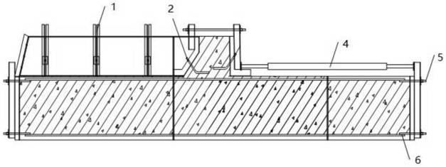
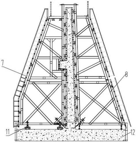
[0046] Such as Figures 1 to 7 As shown, a specific implementation method for the pouring and forming construction technology of the buttress rib beam type wall body of a large sewage pool is provided. The current reinforced concrete sewage pool is divided into two steps of construction. Reinforcement production, installation, formwork and pouring are carried out on the pool wall, resulting in the waste water pool taking too long in the entire pre-drilling construction period. At the same time, after the waste water pool is delivered for use, it often fails to meet the design strength requirements due to insufficient maintenance periods. In this embodiment, the collected potato starch wastewater is mainly pretreated and adjusted for storage. The designed sewage pool wall is 8.5m in height, 0.6m in bottom width, and 0.3m in top width. Rib beams of 0.5m*0.5m, in addition, there are triangular arm ...


PUM


Abstract

The invention relates to the technical field of building construction, in particular to a pouring forming construction process for a large sewage pool supporting arm ribbed beam type wall body. The gradient of the inner side of the inner side face of the wall body formed through pouring is 3.6%, ribbed beams are arranged on the outer side of the wall body, a plurality of triangular supporting armwalls are arranged on the outer side of the wall body, and the interval between every two adjacent triangular supporting arm walls is uniform. When the wall body is constructed, an inner side formwork, an outer side formwork and a foundation formwork need to be adopted. The inner side formwork comprises an inner wall surface formwork, an inner triangular truss, an inner side pull rod and an innerformwork back edge. The outer side formwork comprises an outer wall surface formwork, an outer triangular truss, an outer formwork back edge, a supporting arm formwork, a supporting arm back edge, a ribbed beam formwork, an outer side pull rod, an outer side connecting rod, an outer side wall plug formwork and a supporting arm cover plate. The pouring forming construction process aims to solve theproblems of existing engineering reinforced concrete wastewater pool pouring, the construction time of an engineering wastewater pool is shortened, the whole construction period is shortened and theleakage problem caused by construction joints is avoided.

Description

technical field [0001] The invention relates to the technical field of building construction, in particular to a pouring and forming construction process for a large-scale sewage pool with a rib-beam wall body. Background technique [0002] The present reinforced concrete wastewater pool is divided into two-step construction, the cushion layer is poured earlier, and the pool wall is made, installed, formworked and poured after leaving the construction joints. As a result, the wastewater pool takes too long in the entire pre-drilling construction period. At the same time, after the wastewater pool is delivered for use, it often fails to meet the design strength requirements due to insufficient maintenance periods. [0003] "Petroleum Engineering Construction" No. 05, 1990 disclosed a continuous pouring of a reinforced concrete pool, which adopts the method of continuous pouring of grout in layers, and completes all pouring of concrete from the bottom of the pool to the wall o...

Claims


Application Information

Patent Timeline
IPC IPC(8): E04B2/00E04G9/06E04G11/08E04G19/00E04G17/14E04G17/00E02D27/01
CPCE04B2/00E04G11/08E04G19/00E04G17/14E04G17/00E02D27/01
Inventor 南玉明刘世明刘力刘丽娟窠旭亮赵志诚
Owner 青海玉明金属结构制造有限公司
Why Eureka
Try Eureka