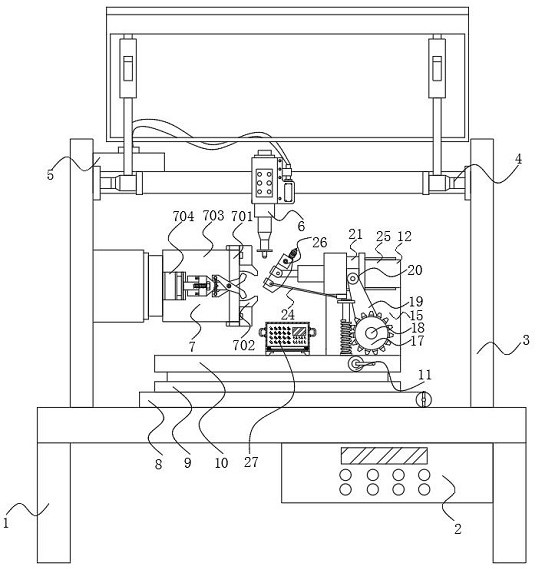
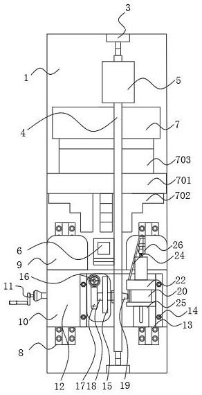
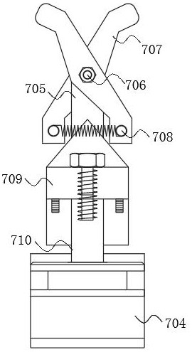
Fault diagnosis machining equipment for pin hole driving sphere

A technology for fault diagnosis and processing equipment, applied in metal processing equipment, measuring/indicating equipment, metal processing machinery parts, etc., can solve problems such as inaccurate position of the tool, influence of ball valve sealing, rapid response of processing process, etc., to achieve High work efficiency and avoid occlusion effect

Inactive Publication Date: 2020-12-04
深圳市康瑞龙数控科技有限公司
View PDF0 Cites 3 Cited by
  • Summary
  • Abstract
  • Description
  • Claims
  • Application Information

AI Technical Summary

Problems solved by technology

[0002] The pin-hole drive ball is mainly used to cut, distribute and change the flow direction of the medium in the pipeline. The pin-hole drive ball is widely used in petroleum refining, long-distance pipeline, chemical municipal, steel and other industries. At present, for the ball Workpiece, end surface polishing device is the most common type of finishing device on the market, but most of the device's workpiece trajectory is relatively simple, and the accuracy of the inner spherical surface (spherical deviation, ball diameter variation and surface roughness) directly affects The technical indicators such as the motion accuracy, noise and life of the pin-hole driven ball will affect the performance of equipment and instruments
[0003] The common problems of the existing non-standard ball processing equipment are: there is a cylindrical hole in the middle of the ball, and the existing groove processing of the ball valve ball needs to lock the ball valve ball, and then use the cutting mach...

Method used


Image

  • Fault diagnosis machining equipment for pin hole driving sphere
  • Fault diagnosis machining equipment for pin hole driving sphere
  • Fault diagnosis machining equipment for pin hole driving sphere

Examples


Embodiment Construction

[0028] The following will clearly and completely describe the technical solutions in the embodiments of the present invention with reference to the accompanying drawings in the embodiments of the present invention. Obviously, the described embodiments are only some, not all, embodiments of the present invention.

[0029] In the description of the present invention, unless otherwise stated, the meaning of "plurality" is two or more; the terms "upper", "lower", "left", "right", "inner", "outer" , "front end", "rear end", "head", "tail", etc. indicate the orientation or positional relationship based on the orientation or positional relationship shown in the drawings, and are only for the convenience of describing the present invention and simplifying the description, rather than Indicates or implies that the device or element referred to must have a particular orientation, be constructed and operate in a particular orientation, and therefore should not be construed as limiting the...


PUM


Abstract

The invention discloses fault diagnosis machining equipment for a pin hole driving sphere, and relates to the technical field of machining of non-standard spheres. The fault diagnosis machining equipment specifically comprises a base, a composite clamp mechanism, an adjustable rotary turning mechanism, an inner spherical surface machining pin and a fault monitoring mechanism; an operation table isarranged at one side of the bottom end of the base; and an indicating lamp is arranged at the middle end of a dust-proof housing. According to the fault diagnosis machining equipment for the pin holedriving sphere, through the arrangement of the composite clamp mechanism, the outer spherical surface and the inner spherical surface of a non-standard sphere can be independently clamped to ensure that the machining position of a workpiece cannot be shielded in a clamping process; through a movable connection design of a spatial shaft sleeve and a sliding groove which is formed between bearings,the workpiece is clamped by clamping jaws when the inner spherical surface is machined by a machine tool; a spline pin opening mechanism is located inside a chamber below a chuck to prevent the influence on the machining position; when the outer spherical surface is machined by the machine tool, the clamping jaws of the chuck are driven to move downwards by the spatial shaft sleeve; the spline pin opening mechanism is used for clamping the inner spherical surface; a streamline design is adopted; and the higher work efficiency achieved.

Description

technical field [0001] The invention relates to the technical field of non-standard sphere processing, in particular to a fault diagnosis processing equipment for pin-hole driving spheres. Background technique [0002] The pin-hole drive ball is mainly used to cut, distribute and change the flow direction of the medium in the pipeline. The pin-hole drive ball is widely used in petroleum refining, long-distance pipeline, chemical municipal, steel and other industries. At present, for the ball Workpiece, end surface polishing device is the most common type of finishing device on the market, but most of the device's workpiece trajectory is relatively simple, and the accuracy of the inner spherical surface (spherical deviation, ball diameter variation and surface roughness) directly affects The technical indicators such as the motion accuracy, noise and life of the pin-hole driven ball will affect the performance of equipment and instruments. [0003] The common problems of the...

Claims


Application Information

Patent Timeline
IPC IPC(8): B23Q17/00
CPCB23Q17/008
Inventor 洪颖何志鹏任禄鑫
Owner 深圳市康瑞龙数控科技有限公司
Why Eureka
Try Eureka