Method for controlling drilling hole sites of aircraft structural parts

A technology of aircraft structural parts and control methods, applied in special data processing applications, instruments, electrical digital data processing, etc., can solve the problems of rigid structure hole drilling hole position deviation and high quality risk

Active Publication Date: 2020-12-04
CHENGDU AIRCRAFT INDUSTRY GROUP
View PDF8 Cites 4 Cited by
  • Summary
  • Abstract
  • Description
  • Claims
  • Application Information

AI Technical Summary

Problems solved by technology

[0004] Aiming at the problems of hole position deviation and high quality risk of weakly rigid structures of aircraft structural parts, a method for controlling the hole position of aircraft structural parts that can avoid the above situations is proposed.

Method used


Image

  • Method for controlling drilling hole sites of aircraft structural parts
  • Method for controlling drilling hole sites of aircraft structural parts
  • Method for controlling drilling hole sites of aircraft structural parts

Examples


Embodiment 1

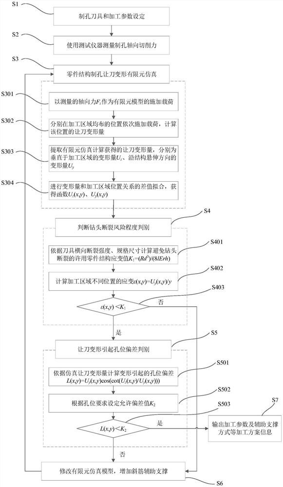
[0046] A method for controlling hole positions of aircraft structural parts, comprising the steps of:

[0047] The first step: setting of hole making tool and processing parameters;

[0048] Furthermore, the first step is specifically: facing the material characteristics of the processed parts, comprehensively considering factors such as hole diameter, surface quality, cutting force and vibration, selecting the hole-making tool and processing parameters for processing the part, and selecting the hole-making tool and processing parameters for the machining of the part. In this case, the hole making meets the processing quality requirements.

[0049] Step 2: Use a measuring instrument to measure the axial cutting force of the hole;

[0050] Furthermore, the second step is specifically: use cutting force testing equipment, design the test piece and conduct cutting tests according to the hole-making tool and processing parameters selected for part processing, collect cutting forc...

Embodiment 2

[0077] The present invention proposes a method for controlling the position of holes in aircraft structural parts, and the specific implementation contents are as follows:

[0078] S1: Hole making tool and processing parameter setting

[0079] Facing the material characteristics of the processed part 1, comprehensively considering the factors such as the hole diameter, surface quality, cutting force and vibration, the hole-making tool and processing parameters for the processing of the part 1 are selected, and the hole making under the working condition with good rigidity meets the processing quality Requirements, in this example, a twist drill with a diameter of 6mm is used, the cutting parameters are the speed of 1000mm / min, the feed rate of 100mm / r, the through hole 2 is made, and the cutting fluid is poured.

[0080] S2: Use measuring instruments to measure the axial cutting force of hole making

[0081] Use the cutting force testing instrument, use the hole-making tool a...


PUM

PropertyMeasurementUnit
Diameteraaaaaaaaaa

Abstract

The invention relates to the field of aircraft structural part numerical control machining, in particular to a method for controlling drilling hole sites of aircraft structural parts, which comprisesthe steps of selecting a part drilling cutter and cutting parameters, measuring drilling axial force, performing finite element simulation of part weak-rigidity structure drilling cutter relieving deformation to acquire relationships Uy (x, y) and Uz (x, y) between deformation and a machining area position, judging the fracture risk degree of the drill bit, calculating an allowable structure strain value, judging whether the transverse strain of a machining area is within an allowable range or not, judging hole site deviation caused by cutter relieving deformation, calculating the caused holesite deviation, and judging whether the hole site deviation caused by deformation meets the hole site requirement or not; if the hole site deviation caused by transverse strain or deformation does notmeet the allowable requirement, adding an inclined rib support to the part structure, carrying out simulation calculation again, setting the size and position of the inclined rib, and iterating untilthe transverse strain and deformation hole site deviation meets the requirement, so as to realize the effective control of the hole site of the hole in the weakly rigid region of the aircraft structural member. A quality problem that the drilling position is out of tolerance is avoided.

Description

technical field [0001] The application relates to the field of numerical control machining of aircraft structural parts, in particular to a method for controlling hole positions of aircraft structural parts. Background technique [0002] Due to the performance requirements of high speed and high maneuverability of the aircraft, the structure of the aircraft structural parts is complex and has many thin-walled structures. The weakly rigid thin web and edge structures have large tool deformation during the processing process, resulting in deviations in processing dimensions. There are many hole structures on the thin edge strips of aircraft structural parts, which are used for assembly connection between structural parts. In order to ensure the shape and position accuracy of the structural parts after assembly, the machining accuracy of the thin-walled structural holes of the structural parts is relatively high. However, due to the deformation of the thin-walled structure by t...

Claims


Application Information

Patent Timeline
IPC IPC(8): G06F30/23G06F30/15G06F30/17B23B35/00G06F119/14
CPCB23B35/00G06F30/15G06F30/17G06F30/23G06F2119/14
Inventor 姜振喜宋戈孙超李卫东沈昕王伟王灿
Owner CHENGDU AIRCRAFT INDUSTRY GROUP
Why Eureka
Try Eureka