Driving circuit of symmetrical half-bridge resonance open-loop direct-current proportional converter
A drive circuit and proportional conversion technology, which is applied in the drive circuit field of a symmetrical half-bridge resonant open-loop DC proportional converter, can solve problems such as complex compensation network design optimization, complex feedback control circuit, and no way to individually adjust the front edge, etc., to achieve Achieve saturated conduction and fast turn-off, ensure tolerance design, and high reliability
- Summary
- Abstract
- Description
- Claims
- Application Information
AI Technical Summary
Problems solved by technology
Method used
Image

Examples
Embodiment 1
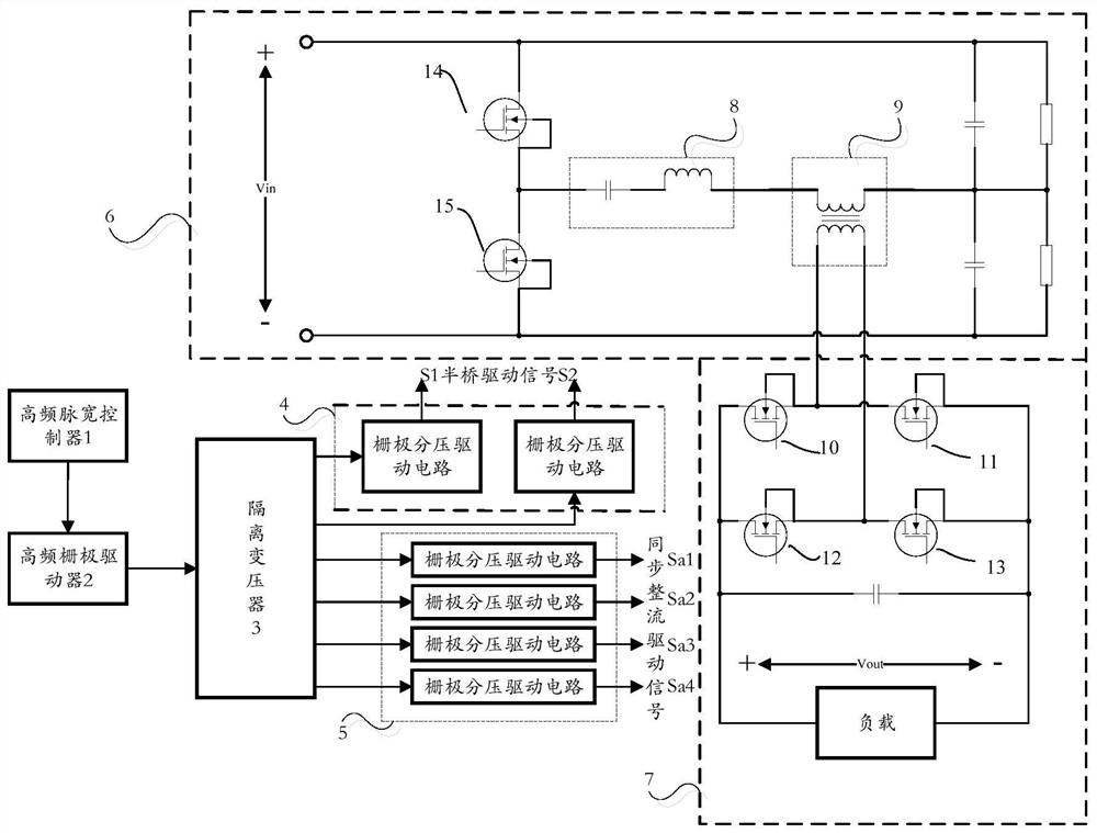
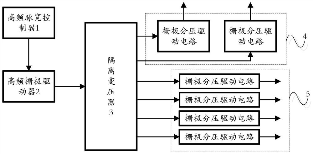
[0028] Such as figure 1 As shown, the symmetrical half-bridge resonant open-loop DC proportional converter in this embodiment includes a resonant circuit 6 and a rectifier circuit 7, wherein the resonant circuit 6 is composed of two half-bridge transistors, two equalizing capacitors, two equalizing A symmetrical half-bridge resonant circuit formed by a resistor and a high-frequency transformer 9, the rectifier circuit 7 is a synchronous rectification circuit composed of four synchronous rectification transistors and a filter capacitor, and the four synchronous rectification transistors are connected to the secondary end of the high-frequency transformer 9 to drive The circuit is connected to two half-bridge transistors and four synchronous rectification transistors.
[0029] Further, the symmetrical half-bridge resonant open-loop DC proportional converter further includes an LC series resonant circuit 8 connected between the primary end of the high-frequency transformer 9 and ...
Embodiment 2
[0058] This embodiment provides a driving method for a symmetrical half-bridge resonant open-loop DC proportional converter. The driving method is suitable for driving the driving circuit of the symmetrical half-bridge resonant open-loop DC proportional converter in the above embodiment. The method includes: step 1, connecting an LC series resonant circuit in series between the primary side of the high-frequency transformer and the resonant circuit; step 2, determining the switching frequency of the drive circuit according to the resonant angular frequency of the LC series resonant circuit; step 3, according to the switching frequency , sending a transistor turn-on instruction to the drive circuit, where the transistor turn-on instruction is used to control the transistor in the drive circuit to turn on or off.
[0059] The technical solution of the present application has been described in detail above in conjunction with the accompanying drawings. The present application prop...
PUM
 Abstract
Description
Claims
Application Information
 - R&D
- Intellectual Property
- Life Sciences
- Materials
- Tech Scout
- Unparalleled Data Quality
- Higher Quality Content
- 60% Fewer Hallucinations
Browse by: Latest US Patents, China's latest patents, Technical Efficacy Thesaurus, Application Domain, Technology Topic, Popular Technical Reports.
© 2025 PatSnap. All rights reserved.Legal|Privacy policy|Modern Slavery Act Transparency Statement|Sitemap|About US| Contact US: help@patsnap.com