
Miniaturized ultra-wideband microwave millimeter wave signal generator

A signal generator, millimeter wave technology, applied in the direction of electrical components, power automatic control, etc., can solve the problems of expensive, bulky, large signal generator, etc., to achieve small commissioning workload, low cost, consistent batch good sex effect

Pending Publication Date: 2020-12-04
西安豹斐电子科技有限公司
View PDF0 Cites 2 Cited by
  • Summary
  • Abstract
  • Description
  • Claims
  • Application Information

AI Technical Summary

Problems solved by technology

To achieve ultra-wideband frequency coverage, it needs to be divided into many frequency bands. The entire signal generator is bulky, heavy, and extremely expensive.

Method used


Image

  • Miniaturized ultra-wideband microwave millimeter wave signal generator
  • Miniaturized ultra-wideband microwave millimeter wave signal generator

Examples


Embodiment 1

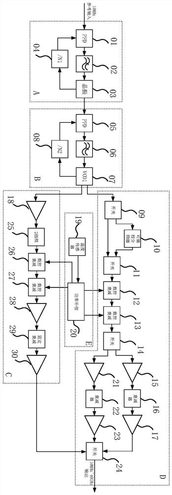
[0020] refer to figure 1 , two phase-locked loops are set, which are respectively a reference phase-locked crystal oscillator circuit and a main phase-locked loop. The reference phase-locked crystal oscillator circuit includes a phase-frequency detector (PFD) 01 for input signals, and a phase-frequency detector (PFD) 01 electrically connected to the phase-frequency detector 01. Low-pass loop filter 02, programmable frequency divider 04 electrically connected with low-pass loop filter 02 constant temperature crystal oscillator 03 and constant temperature crystal oscillator 03, programmable frequency divider 04 is also connected with frequency discrimination The phase detector 01 is electrically connected, the difference between the main phase-locked loop and the reference phase-locked crystal oscillator circuit is that the constant temperature crystal oscillator is replaced by a voltage-controlled oscillator (VCO1) 07; the original signal is processed by the reference phase-lock...

Embodiment 2

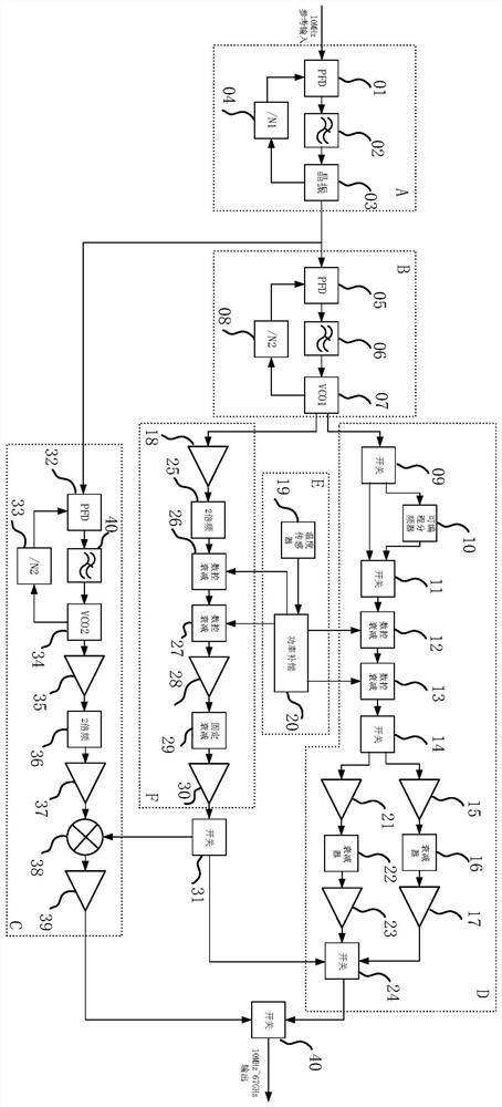
[0028] refer to figure 2, the difference from embodiment 1 is that the 100MHz signal output from the constant temperature crystal oscillator in the reference phase-locked crystal oscillator circuit is divided into two paths, one path is similar to the method in embodiment 1, and finally outputs a 10MHz-40GHz signal from the SPTT switch 24 , at the same time, another path passes through the phase-locked loop formed by the frequency and phase detector 32, the low-pass loop filter 40, the voltage-controlled oscillator 34 and the programmable frequency divider 33, and obtains the output by the voltage-controlled oscillator 34 11GHz, 13.5GHz, 16GHz, 19.5GHz and 20GHz five point frequency signals, and then the point frequency signal is amplified by the amplifier 35 to drive the 2 times frequency multiplier 36 to output five point frequency signals of 22GHz, 27GHz, 32GHz, 39GHz and 40GHz , and then continue to reach the mixer 38 through the amplifier 37, the 18GHz~23GHz signal outpu...


PUM


Abstract

The invention relates to a miniaturized ultra-wideband microwave millimeter wave signal generator. The signal generator comprises a plurality of phase-locked loops connected in sequence, a frequency mixing circuit, a frequency doubling amplification circuit connected with the phase-locked loops, and a power compensation circuit connected with the frequency mixing circuit and the frequency doublingamplification circuit. Signals output by the phase-locked loops are divided into two paths, one path outputs frequency mixing signals after passing through the frequency mixing circuit, the other path outputs amplification signals through the frequency doubling amplification circuit, and the two paths of output signals output microwave and millimeter wave signals after frequency summation. The power compensation circuit is respectively connected with the frequency mixing circuit and the frequency doubling amplification circuit and is used for compensating the power of signals in the frequencymixing circuit and the frequency doubling amplification circuit. After the technical scheme is adopted, the ultra-wideband microwave millimeter signal generator provided by the invention realizes product miniaturization, low cost and high index through the design of the circuit; and meanwhile, the product is easy to produce and process, good in batch consistency and small in debugging and testingworkload.

Description

technical field [0001] The invention relates to the field of ultra-wideband microwave signal generators in the field of radio communication, in particular to a miniaturized ultra-wideband microwave and millimeter wave signal generator. Background technique [0002] Microwave and millimeter wave signal generators are electronic devices that generate extremely high frequency signals. Microwave signals refer to electromagnetic waves with a frequency of 300MHz to 300GHz and corresponding wavelengths in the range of 1mm to 1m. Among them, signals with wavelengths on the order of millimeters are called millimeter waves. . Due to the characteristics of microwave and millimeter wave itself, the lumped components used in conventional circuit theory have failed in the microwave and millimeter wave frequency bands. Microwave devices are usually distributed components, the circuit size and the wavelength corresponding to the operating frequency are of the same order of magnitude, and t...

Claims


Application Information

Patent Timeline
Patent Type & Authority Applications(China)
IPC IPC(8): H03L7/26
CPCH03L7/26
Inventor 王宝平李昂王卫涛
Owner 西安豹斐电子科技有限公司
Learn More