
Fluidized bed device for preparing uranium nitride and using method thereof

A technology of fluidized bed and uranium nitride, which is applied in the field of nuclear engineering, can solve the problems of less research on special equipment, and achieve the effect of thorough tail gas disposal and high reaction yield

Active Publication Date: 2020-12-08
HEFEI INSTITUTES OF PHYSICAL SCIENCE - CHINESE ACAD OF SCI
View PDF5 Cites 0 Cited by
  • Summary
  • Abstract
  • Description
  • Claims
  • Application Information

AI Technical Summary

Problems solved by technology

The above research mainly focuses on method research, and there are few researches on special equipment for the preparation of uranium nitride, and all of them are intermittent production equipment.

Method used


Image

  • Fluidized bed device for preparing uranium nitride and using method thereof
  • Fluidized bed device for preparing uranium nitride and using method thereof
  • Fluidized bed device for preparing uranium nitride and using method thereof

Examples


Embodiment 1

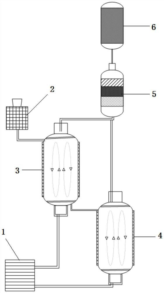
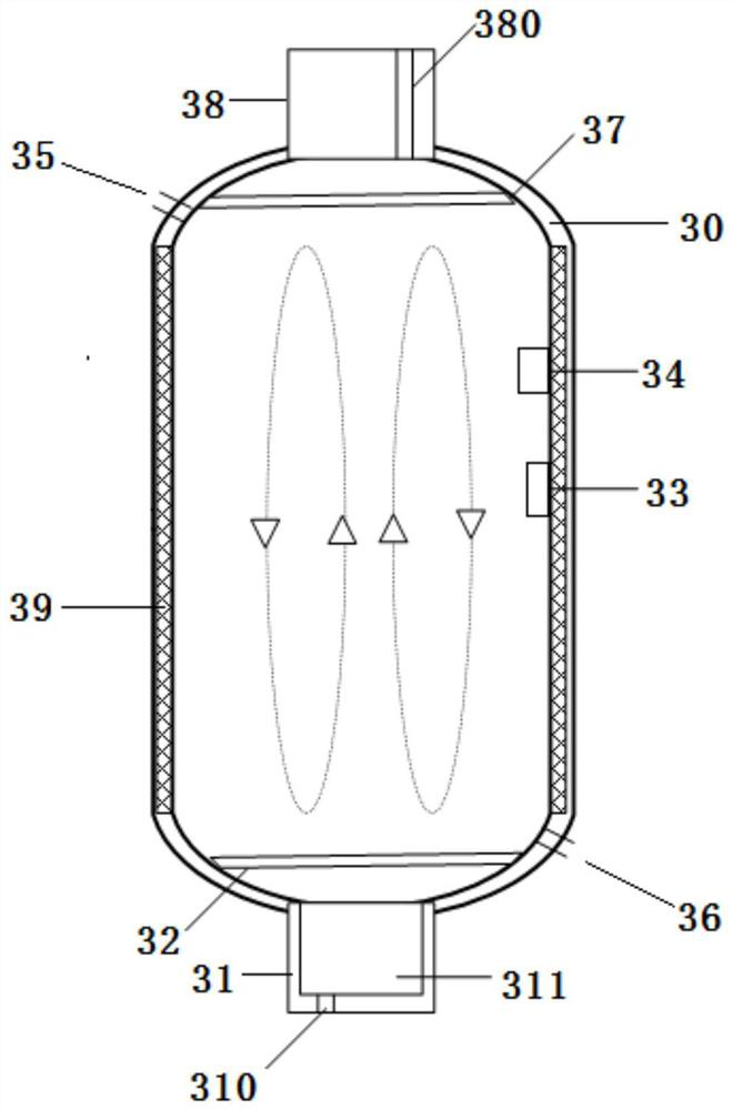
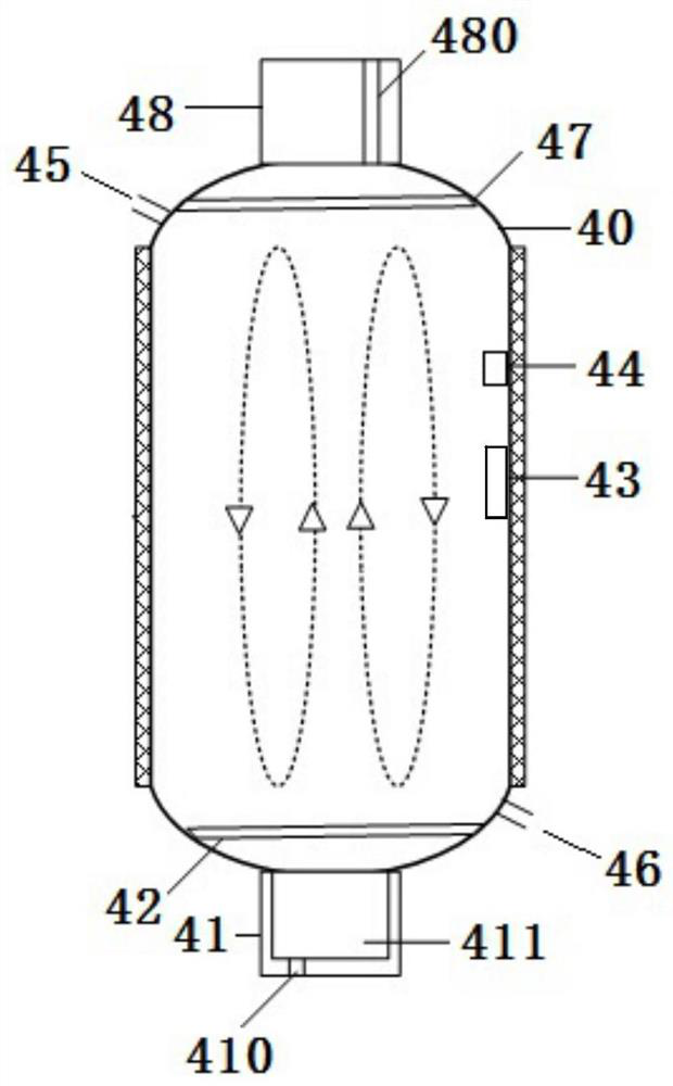
[0031] A fluidized bed device for preparing uranium nitride, comprising a gas system 1, a mixing system 2, a low-temperature fluidized bed 3, a high-temperature fluidized bed 4, a tail gas treatment device 5 and an absorption tower 6; the gas system 1 Connect with low temperature fluidized bed 3, high temperature fluidized bed 4 respectively, described mixing system 2 is connected with low temperature fluidized bed 3, described low temperature fluidized bed 3 is connected with high temperature fluidized bed 4, described low temperature fluidized bed 3. The high-temperature fluidized bed 4 is connected to the tail gas treatment device 5 respectively, and the tail gas treatment device 5 is connected to the absorption tower 6 .

[0032] In this embodiment, by controlling the reaction steps in a low-temperature fluidized bed and a high-temperature fluidized bed respectively, the smooth progress of the reaction under different temperature requirements is ensured; the reaction condit...

Embodiment 2

[0046] In order to achieve the above purpose, this embodiment also provides a method for using a fluidized bed device for preparing uranium nitride, comprising the following steps:

[0047] S1, UO 2 with NH 4 HF 2 With a molar ratio of 1:4 to 1:8 or U 3 o 8 with NH 4 HF 2 Put it into a mixing device at a molar ratio of 1:12 to 1:24, mix and grind in the mixing device for 30-60 minutes to obtain ground powder particles;

[0048] S2, feed argon gas into the low-temperature fluidized bed, and wash repeatedly 3 times;

[0049] S3. Transfer the ground powder particles after mixing and grinding to a low-temperature fluidized bed, heat to 20-125°C through the first heating device and the first temperature control sensor, and react for 3-12 hours to obtain a reaction product;

[0050] S4, transfer the reaction product to a high-temperature fluidized bed, and feed Ar and NH 3 , N 2 、H 2 The combined gas mixed gas is heated to 700-1000°C by the second heating device and the se...


PUM


Abstract

The invention provides a fluidized bed device for preparing uranium nitride. The fluidized bed device comprises a gas system, a mixing system, a low-temperature fluidized bed, a high-temperature fluidized bed, a tail gas treatment device and an absorption tower; wherein the gas system is respectively connected with the low-temperature fluidized bed and the high-temperature fluidized bed, the mixing system is connected with the low-temperature fluidized bed, the low-temperature fluidized bed is connected with the high-temperature fluidized bed, the low-temperature fluidized bed and the high-temperature fluidized bed are respectively connected with the tail gas treatment device, and the tail gas treatment device is connected with the absorption tower. The invention further provides a using method of the fluidized bed device for preparing uranium nitride. According to the invention, the reaction steps are respectively controlled to be carried out in the low-temperature fluidized bed and the high-temperature fluidized bed, so that the reaction can be carried out smoothly under different temperature requirements; and the tail gas is purified in the tail gas treatment device, so that thedischarged gas has no pollution to the environment. The method can ensure high uranium nitride preparation reaction yield and complete tail gas treatment.

Description

technical field [0001] The invention relates to the technical field of nuclear engineering, in particular to a fluidized bed device for preparing uranium nitride and a use method thereof. Background technique [0002] Nuclear energy is a clean, efficient and safe energy source, and currently occupies an important position in the world's energy structure. In recent years, with the development of the nuclear industry, various advanced reactors have been extensively studied. With the gradual miniaturization of reactors, long refueling periods, and metal cooling, new requirements are constantly being put forward for nuclear fuel as the core material of reactors: high melting point, high thermal conductivity, high atomic density of heavy metals, and compatibility with cladding materials and coolants High, low expansion, low fission gas release and manufacturability, that is, good fuel breeding performance, high thermal conductivity, high thermal stability, good chemical compatib...

Claims


Application Information

Patent Timeline
IPC IPC(8): B01J8/26B01F13/10B01D53/68B01D53/58B01D53/18B01D53/30C01B21/06G21C3/58
CPCB01J8/26B01J8/1872B01J8/1836B01D53/68B01D53/58B01D53/18B01D53/30C01B21/063G21C3/58B01J2208/00061B01J2208/00884B01D2257/2047B01D2251/404B01D2251/304B01D2251/604B01D2251/502B01F33/80B01F33/8362B01F33/83613Y02E30/30
Inventor 孙永菊梅华平李桃生
Owner HEFEI INSTITUTES OF PHYSICAL SCIENCE - CHINESE ACAD OF SCI
Learn More