Preparation method of waterway backboard for target material

A technology of back plate and waterway, which is applied in the field of target materials, can solve the problems of short service life of the friction stir head, reduce the quality of the stirring layer, and insufficient heat input, etc., and achieve the effect of increasing the welding rate, small deformation, and good mechanical properties

Active Publication Date: 2020-12-08
FUJIAN ACETRON NEW MATERIALS CO LTD
View PDF12 Cites 4 Cited by
  • Summary
  • Abstract
  • Description
  • Claims
  • Application Information

AI Technical Summary

Problems solved by technology

Electron beam welding has high requirements on the welding environment. It must be in a vacuum environment, and the appearance of the surface after mechanical processing has obvious welding marks; the friction stir welding process will bring foreign matter such as oxides and oil stains on the back plate into the weld seam, reducing the stirring layer. However, there are disadvantages such as slow warm-up, insufficient heat input and defects, low welding efficiency, and short service life of the friction stir head.

Method used


Image

  • Preparation method of waterway backboard for target material
  • Preparation method of waterway backboard for target material
  • Preparation method of waterway backboard for target material

Examples


Embodiment 1

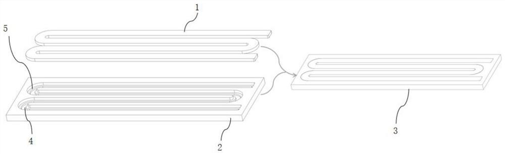
[0031] Such as Figure 1 to Figure 3 Shown: This embodiment provides a method for preparing a target waterway backplane, including the following steps:

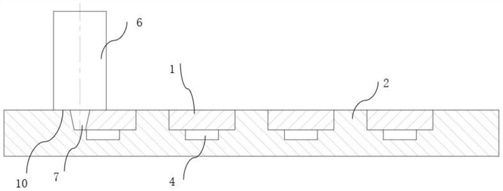
[0032] (1) Process a T-shaped groove on the copper backplane main body 2, the T-shaped groove includes a cover plate groove 5 and a water tank 4 arranged from top to bottom, the width of the cover plate groove 5 is greater than the width of the water tank 4; the copper backplane main body 2 Oxygen-free copper plate is used, the length is 500mm, the width is 150mm, the thickness is 20mm, and the hardness is 87HV;

[0033] (2) Place the cover plate 1 on the cover plate groove 5 to obtain the waterway copper back plate 3 to be welded. The cover plate 1 is also made of oxygen-free copper plate. The cover plate 1 matches the cover plate groove 5, and the cover plate 1 and the cover plate groove The gap between 5 is within 0.2mm, and then the cover plate 1 is pressed tightly with the pressure plate, so as to fix the cover plate 1 ...

Embodiment 2

[0043] Such as Figure 4 As shown, this example adopts a separate friction stir welding method, and the process flow and parameters are the same as in Example 1:

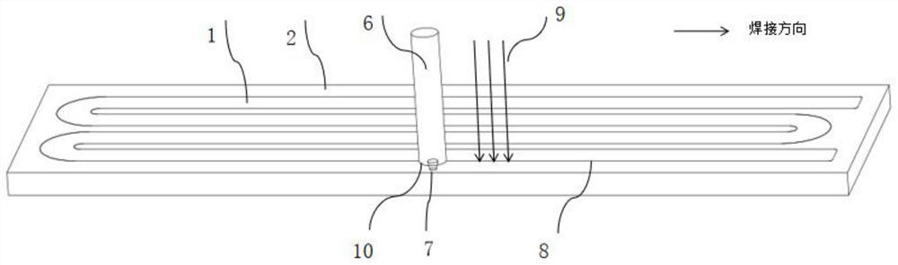
[0044] After the cover plate 11 is covered on the copper back plate main body 22, after spot welding and one-time welding, the welding needle 77 of the friction stir head 6 gradually rotates into the joint 8 of the copper back plate main body 22 and the cover plate 11, and the speed is 600r / min, feed rate: 230mm / min, the shoulder 1010 of the friction stirring head 6 extends to the contact surface and presses down 0.2-0.5mm, the welding pin 77 of the friction stirring head 6 after preheating is along the main body 22 of the copper backboard and the cover The fused seam 88 of the plate 11 moves and the welding needle 7 rotates to generate frictional heat, so that the temperature of the material at the seam 8 rises and plastic deformation occurs, and heat is generated by friction between the shoulder 1010 of the frict...

Embodiment 3

[0047] Such as Figure 4 As shown, in this example, on the basis of Example 2, the welding speed is reduced by about half compared with Example 2:

[0048] After the cover plate 11 is covered on the copper back plate main body 22, after spot welding and one-time welding, the welding needle 77 of the friction stir head 6 gradually rotates into the joint 8 of the copper back plate main body 22 and the cover plate 11, and the speed is 600r / min, feed rate: 130mm / min, the shoulder 1010 of the friction stirring head 6 extends to the contact surface and presses down 0.2-0.5mm, the welding pin 77 of the friction stirring head 6 after preheating is along the main body 22 of the copper backboard and the cover The fused seam 88 of the plate 11 moves and the welding needle 7 rotates to generate frictional heat, so that the temperature of the material at the seam 8 rises and plastic deformation occurs, and heat is generated by friction between the shoulder 1010 of the friction stir head 6...


PUM

PropertyMeasurementUnit
hardnessaaaaaaaaaa
hardnessaaaaaaaaaa
hardnessaaaaaaaaaa

Abstract

The invention discloses a preparation method of a waterway backboard for a target material. The preparation method is characterized by comprising the following steps that (1) a T-shaped groove is machined in a copper backboard body, and the T-shaped groove comprises a cover plate groove and a water groove which are arranged from top to bottom; (2) a cover plate is placed on the cover plate groove,and a to-be-welded waterway copper backboard is obtained; (3) a welding workpiece is fixed to a rigid tool; (4) a laser device is arranged above the to-be-welded waterway copper backboard; (5) spot welding is conducted on the to-be-welded waterway copper backboard; (6) primary welding is conducted; and (7) secondary welding is conducted, specifically, a welding needle is gradually rotated into ajoint, a focus is located at the joint between the copper backboard body and the cover plate, then a stirring friction head and the laser device are started at the same time, and the stirring frictionhead and the focus are fed synchronously in the welding direction according to the same feeding amount. According to the preparation method of the waterway backboard for the target material, the welding efficiency of the waterway backboard for the target material is improved, and the service life of the stirring friction head is prolonged.

Description

technical field [0001] The invention relates to the technical field of targets, in particular to a method for preparing a target water channel back plate. Background technique [0002] In the process of magnetron sputtering, due to the continuous bombardment of high-speed particles on the target, the kinetic energy is converted into heat energy, and the target will generate a lot of heat. If the heat cannot be transferred in time, it will cause deformation of the target and the back plate, resulting in distortion of the back plate. It affects the use effect of the backplane, and at the same time causes the target to overheat and cause off-target phenomenon. The heat generated will also affect the characteristics of the substrate film formed by sputtering. Therefore, the target temperature must be controlled within a certain range, and it is of great significance to develop a waterway copper backplane with high-efficiency cooling function. [0003] At present, the commonly u...

Claims


Application Information

Patent Timeline
Patent Type & Authority Applications(China)
IPC IPC(8): B23K26/346B23K20/12
CPCB23K26/346B23K20/12B23K20/122B23K20/1245
Inventor 黄新勇张科苏百樱叶开满陈宗鸿
Owner FUJIAN ACETRON NEW MATERIALS CO LTD
Why Eureka
Try Eureka