
Gate pump remote monitoring system

A remote monitoring system, remote server technology, applied in general control systems, control/regulation systems, program control, etc., can solve problems such as inability to adapt to data transmission efficiency, control instruction data security, work reliability, etc., to enhance work Reliability and stability, improved productivity, reduced overhead costs

Inactive Publication Date: 2020-12-08
宁波科蓝中水信息技术有限公司
View PDF8 Cites 0 Cited by
  • Summary
  • Abstract
  • Description
  • Claims
  • Application Information

AI Technical Summary

Problems solved by technology

[0002] The gate station and pump station monitoring system use computer communication network, automatic control, sensor and other technologies to complete data collection and processing, control and adjustment of unit equipment, fault maintenance, data storage and remote communication. Most of the existing small and medium-sized water conservancy projects are equipped with The local computer monitoring system is mainly used to monitor local water pump facilities, gate facilities, etc., and realizes automatic management to a certain extent. However, for remote monitoring, optimal dispatching and configuration of water resources, etc. can no longer adapt to the combination of gate stations and pump station groups. Requirements for data transmission efficiency, control command data security, work reliability, etc.

Method used


Image

  • Gate pump remote monitoring system

Examples


Embodiment 1

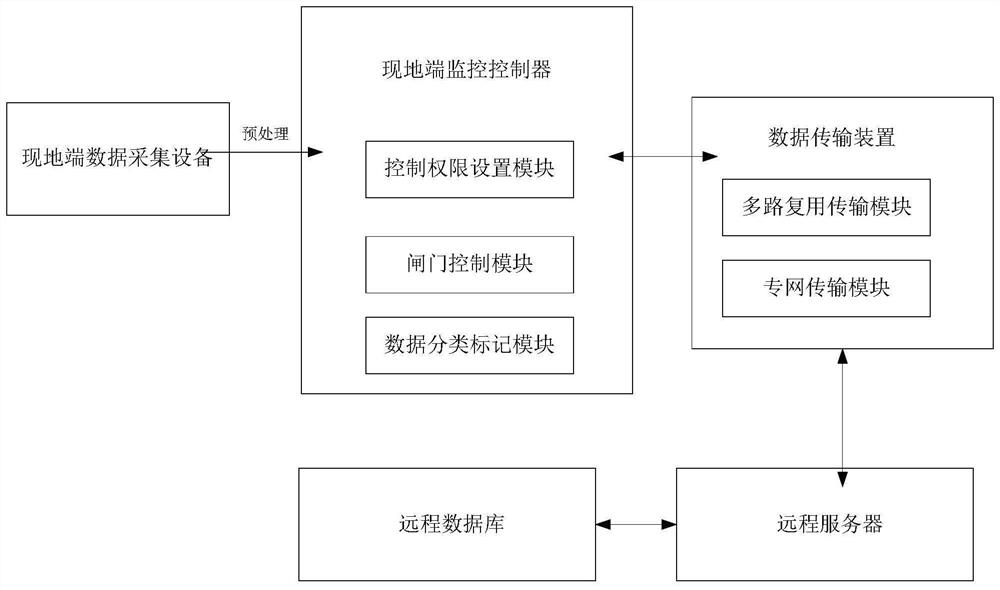
[0027]Such asfigure 1 As shown, a sluice pump remote monitoring system of this embodiment includes a data acquisition device on the site side for collecting data; a data processing module is provided in the data acquisition device on the site side for pre-processing the collected data. Processing; on-site monitoring controller, used to connect with on-site data acquisition equipment, and receive data transmitted by on-site data acquisition equipment; on-site monitoring controller is equipped with gate control module and data classification and marking module And the control authority setting module, the gate control module is used to control the gate, the data classification marking module is used to classify and mark the received data, and the control authority setting module is used to set the priority of control rights of different levels of control users to the same gate; data transmission The device is used to connect with the local monitoring controller, the data transmission ...

Embodiment 2

[0029]Compared with Embodiment 1, in this embodiment, the on-site monitoring controller includes a backup on-site monitoring controller, which switches to the backup on-site monitoring controller when the on-site monitoring controller fails;

[0030]In addition, the on-site monitoring controller includes an encryption module to encrypt sensitive data to ensure data transmission security and control command transmission security; on-site data collection equipment is installed at gate stations, pumping stations, water outlets, and reservoirs ; On-site data acquisition equipment, used to collect water level, flow, gate level and water quality data; On-site monitoring controller includes PLC controller; On-site data acquisition equipment pre-processing is used to eliminate invalid data; this embodiment Set up the data classification marking module and the control authority setting module on the local side. Through the data classification marking, users of different levels can set different...


PUM


Abstract

The invention discloses a gate pump remote monitoring system which comprises in-situ end data acquisition equipment, an in-situ end monitoring controller, a data transmission device, a remote server,a remote database and the like. The automatic control and monitoring capacity of gates and station groups is improved, the reliability of gate and station group control is improved, water conservancyproject management is more scientific, multi-gate-pump combined monitoring, combined water volume dispatching and allocation, real-time remote monitoring and control are achieved, personnel on duty isreduced, and the working efficiency is improved; the data transmission efficiency, safety and control accuracy are improved, and the working reliability and stability are enhanced.

Description

Technical field[0001]The invention relates to the technical field of sluice pump monitoring, and more specifically, to a sluice pump remote monitoring system.Background technique[0002]The monitoring system of gate station and pumping station uses computer communication network, automatic control, sensors and other technologies to complete data collection and processing, and control and adjustment of unit equipment, fault maintenance, data storage and remote communication. Most of the existing small and medium water conservancy projects are configured The local computer monitoring system is mainly used to monitor local water pump facilities, gate facilities, etc., and realizes automatic management to a certain extent. However, for remote monitoring, water resources optimal scheduling configuration, etc., can no longer adapt to the combination of gate stations and pumping stations. Joint regulation requires data transmission efficiency, regulation command data security, and work relia...

Claims


Application Information

Patent Timeline
Patent Type & Authority Applications(China)
IPC IPC(8): G05B19/042
CPCG05B19/0423G05B2219/23051
Inventor 王秋邓立林黄涵
Owner 宁波科蓝中水信息技术有限公司
Learn More