Tunnel furnace

A tunnel furnace and pipeline technology, applied in food ovens, oven air treatment devices, food processing, etc., can solve the problems of poor heating effect, inability to adjust the height of the mesh belt above the conveying chain plate, and inability to adapt to higher heights Product drying effect and other issues to achieve the effect of improving the heating effect

Pending Publication Date: 2020-12-11
志合装备技术(惠州)有限公司
View PDF0 Cites 0 Cited by
  • Summary
  • Abstract
  • Description
  • Claims
  • Application Information

AI Technical Summary

Problems solved by technology

[0004] The purpose of the present invention is to provide a tunnel furnace to solve the problem of the tunnel furnace proposed in the above background technology, which can solve the problem that the height of the mesh belt

Method used


Image

  • Tunnel furnace
  • Tunnel furnace
  • Tunnel furnace

Examples


Embodiment 1

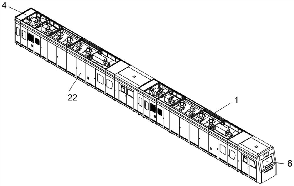
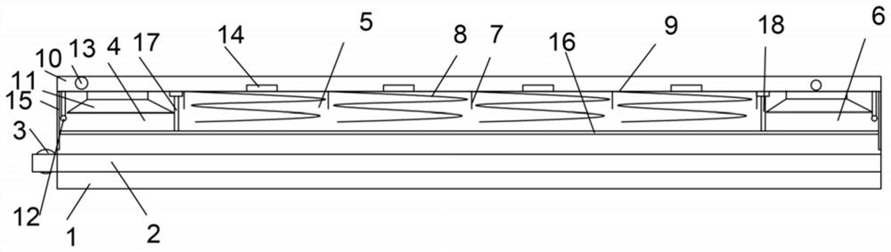
[0030] see Figure 1-Figure 2 , the present embodiment provides a tunnel furnace, including a tunnel furnace body 1, a conveying pipeline 2 for placing products is provided in the tunnel furnace body 1, the side of the conveying pipeline 2 is driven by a first motor 3, and the tunnel furnace The furnace body 1 includes a feed area 4, a heating area 5, and a discharge area 6. The heating area 5 includes more than one heating box 7 arranged from left to right, and a spiral heating wire is arranged inside the heating box 7. 8. A first partition 9 is provided above the tunnel furnace body 1 to isolate the tunnel furnace body 1 from top to bottom. The upper chamber of the tunnel furnace body 1 is used as a waste heat absorption pipe 10, and is connected between the feed area 4 and the outlet An air outlet channel 11 and a high-pressure blower 12 are provided in the material area 6, and an aspirator 13 connected to the corresponding air outlet channel 11 is respectively provided on ...

Embodiment 2

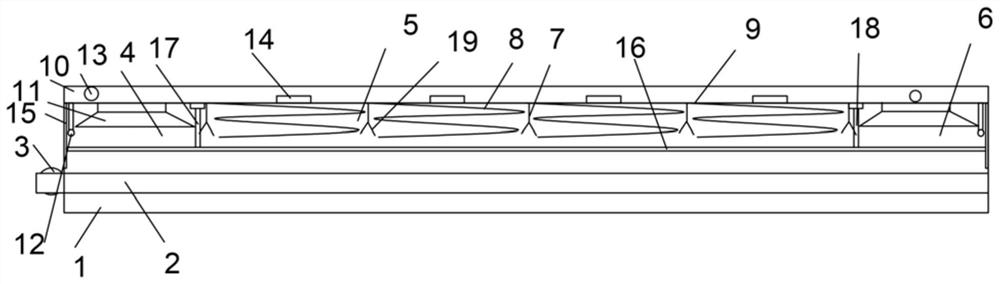
[0034] see image 3 , present embodiment provides a kind of tunnel furnace, further, increase the temperature of heat, further improve heating effect, be provided with the heating plate 19 that obliquely arranges on the both sides of heating box 7, by setting heating plate 19, utilize heating plate 19 to make The generated heat is heated up twice to improve the heating effect on the product.

Embodiment 3

[0036] see Figure 4 , present embodiment provides a kind of tunnel furnace, in order to display conveniently, on the left side of tunnel furnace body 1, be provided with controller 20 and liquid crystal display 21 that control whole equipment work, display internal temperature or data information through liquid crystal display 21.


PUM


Abstract

The present invention discloses a tunnel furnace. The tunnel furnace comprises a tunnel furnace body, a conveying pipeline and a first motor, the tunnel furnace body comprises a feeding area, a heating area and a discharging area, the heating area comprises one or more heating boxes, heating wires are arranged in the heating boxes, a first partition plate for isolating the tunnel furnace body up and down is arranged at an upper portion in the tunnel furnace body, an upper cavity of the tunnel furnace body serves as a waste heat absorption pipeline, air outlet channels and high-pressure air blowers are arranged in the feeding area and the discharging area, suction devices are arranged on two sides of the waste heat absorption pipeline respectively, a conveying pipe communicating with the waste heat absorption pipeline is arranged above each heating box, a vertically-arranged sliding strip is arranged on each of a left side and a right side in the tunnel furnace body, a mesh belt locatedon the conveying pipeline is connected between the two sliding strips in a sliding mode, first air cylinders for driving the mesh belt to move up and down are arranged in the tunnel furnace body, andguide rods penetrating through the mesh belt are further arranged in the tunnel furnace body. The structure can adjust distances between the mesh belt and the conveying pipeline according to a heightof a product.

Description

technical field [0001] The invention relates to the technical field of tunnel furnaces, in particular to a tunnel furnace. Background technique [0002] Tunnel oven (food processing category) is a tunnel-type mechanical equipment that completes food baking through heat conduction, convection, and radiation. The baking chamber is a long and narrow tunnel. There is a continuously operating conveyor system inside the tunnel. When the food is baked, the relative movement between the food through the conveying chain plate, steel belt or mesh belt and the electric heating element or the direct-fired combustion rod is completed, so as to complete the work of uniform baking and conveying. This type of oven can be produced continuously, has high production efficiency, saves manpower, and has stable baking quality. [0003] However, the existing tunnel furnace has the following problems: 1. The height of the mesh belt above the conveying chain plate cannot be adjusted, so it cannot...

Claims


Application Information

Patent Timeline
IPC IPC(8): A21B1/02A21B3/00A21B3/04A21C15/00
CPCA21B1/02A21B3/00A21B3/006A21B3/04A21C15/002Y02P60/80
Inventor 肖平梁华丰杨军
Owner 志合装备技术(惠州)有限公司
Why Eureka
Try Eureka