A tank-type thermal desorption device and desorption method based on thermal desorption additive filling

A technology of thermal desorption and thermal desorption unit, which is applied in the field of polluted soil treatment, can solve the problems of increasing the burden of exhaust gas treatment, residues, and reducing the removal rate of organic pollutants, and achieves improved thermal desorption efficiency, simple structure, and thermal desorption. With remarkable effect

Active Publication Date: 2022-01-28
NANJING INST OF ENVIRONMENTAL SCI MINIST OF ECOLOGY & ENVIRONMENT OF THE PEOPLES REPUBLIC OF CHINA
View PDF7 Cites 0 Cited by
  • Summary
  • Abstract
  • Description
  • Claims
  • Application Information

AI Technical Summary

Problems solved by technology

Most thermal desorption devices use heat to volatilize organic pollutants into waste gas and then treat them, which will increase the burden of tail gas treatment, and some organic matter remains in the soil, resulting in a decrease in the removal rate of organic pollutants

Method used


Image

  • A tank-type thermal desorption device and desorption method based on thermal desorption additive filling
  • A tank-type thermal desorption device and desorption method based on thermal desorption additive filling
  • A tank-type thermal desorption device and desorption method based on thermal desorption additive filling

Examples


Embodiment 1

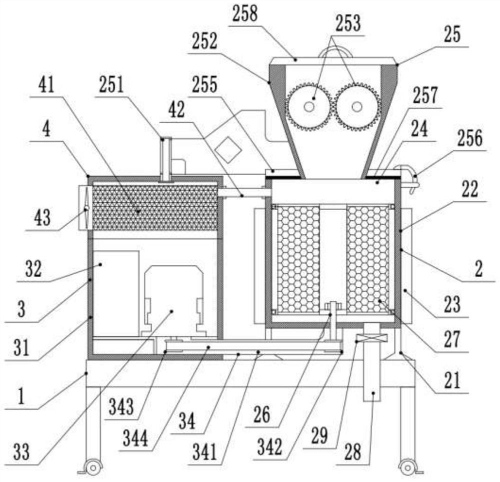
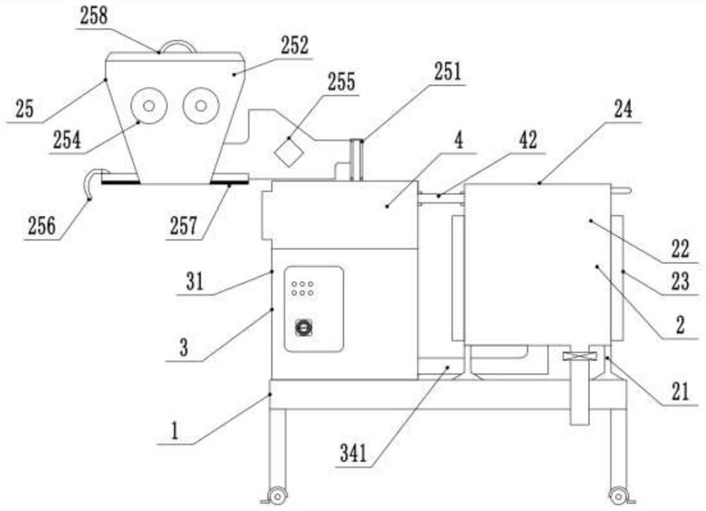
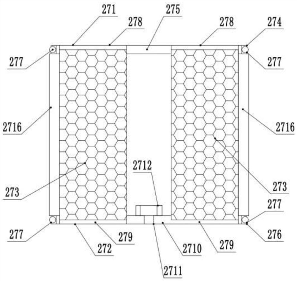
[0030] Such as figure 1 As shown, a tank-type thermal desorption device based on thermal desorption additive filling is characterized in that it includes a support frame 1, and a thermal desorption unit 2, a drive control unit 3, and an exhaust gas treatment unit located above the support frame 1 4; the thermal desorption unit 2 includes a thermal desorption tank 22 connected to the top of the support frame 1 by a support foot 21, and the thermal desorption tank 22 is provided with an electric heating jacket 23 for providing a heat source inside the thermal desorption tank 22, and the thermal desorption tank 22 The top of the desorption tank 22 is provided with a feed inlet 24, the top of the feed inlet 24 is connected with a soil pretreatment mechanism 25, and the center position of the bottom of the thermal desorption tank 22 is provided with a rotating shaft 26, and the upper end of the rotating shaft 26 is detachably connected with The rotary dial 27 filled with thermal de...

Embodiment 2

[0041] This example is basically the same as Example 1, except that the thermal desorption aid only has calcium peroxide particles as the A-type aid.

[0042] After thermal desorption, the removal rate of VOCs benzene was 81.2%, the removal rate of chlorinated organic compounds CVOCs was 79.1%, the removal rate of polycyclic aromatic hydrocarbons PAHs was 76.8%, and the removal rate of polychlorinated biphenyls PCBs was 77.4%.

Embodiment 3

[0044] This embodiment is basically the same as that of Embodiment 1, except that the thermal desorption auxiliary agent is only B-type auxiliary agent adsorbed with alumina balls of hydrogen peroxide solution.

[0045] After thermal desorption, the removal rate of VOCs benzene was 90.1%, the removal rate of chlorinated organic compounds CVOCs was 91.4%, the removal rate of polycyclic aromatic hydrocarbons PAHs was 89.7%, and the removal rate of polychlorinated biphenyls PCBs was 88.5%.


PUM


Abstract

The invention discloses a tank-type thermal desorption device based on thermal desorption auxiliary agent filling and a desorption method thereof. The device includes a support frame, a thermal desorption unit located above the support frame, a drive control unit and an exhaust gas The processing unit, the thermal desorption unit includes a thermal desorption tank with an electric heating jacket on the outside, the bottom of the thermal desorption tank is connected to the rotary dial filled with thermal desorption aids through a rotating shaft, and the drive control unit includes an electric box and The motor and the transmission assembly connected with the rotating shaft; the tail gas treatment unit includes an adsorption box filled with adsorption filler. The present invention uses aluminum oxide balls with adsorbed hydrogen peroxide solution as a low-temperature thermal desorption aid, calcium peroxide as a high-temperature thermal desorption aid, and the soil is fully distributed between two thermal desorption aids by means of the centrifugal rotation of the rotating dial wheel. The paddle of the desorption aid can evenly disperse the oxygen decomposed by heat into the soil, improving the thermal desorption efficiency.

Description

technical field [0001] The invention belongs to the technical field of contaminated soil treatment, in particular to a tank-type thermal desorption device and a desorption method based on thermal desorption additive filling. Background technique [0002] Soil thermal desorption is one of the methods to remove pollutants in organic polluted soil. Heating method is used to heat organic polluted soil to close to or exceed the boiling point of organic matter, so that organic pollutants can be volatilized and separated from the soil, and then the desorbed waste gas processing to achieve the purpose of restoration. Thermal desorption can effectively remove volatile and semi-volatile organic pollutants in soil, such as: volatile organic compounds (VOCs), polycyclic aromatic hydrocarbons (PAHs), polychlorinated biphenyls (PCBs), etc. [0003] The Chinese utility model patent with the publication number CN203578349U discloses an environmentally friendly and energy-saving thermal des...

Claims


Application Information

Patent Timeline
Patent Type & Authority Patents(China)
IPC IPC(8): B09C1/06B02C4/08B02C4/42
CPCB09C1/06B02C4/08B02C4/42
Inventor 石佳奇杨璐龙涛黄剑波应蓉蓉郭洋陈朦温冰
Owner NANJING INST OF ENVIRONMENTAL SCI MINIST OF ECOLOGY & ENVIRONMENT OF THE PEOPLES REPUBLIC OF CHINA
Why Eureka
Try Eureka